Page 2 Model 205ce and 205Mce Operation Manual
CONTENTS
1. Switch Panel - Functions 2
2. Connections - Accessories 2
3. Operation 3
8. Measurements 3
9. Battery Replacement 9
9. Disposal 9
11. Specifications 11
Model 205ce & 205Mce 11
11. Model 601 Accelerometer
12. Severity Chart Back Cover
Balmac assumes no responsibility for errors or
omissions. Neither is any liability assumed for
damages resulting from the use of the information
contained herein.
Specifications are subject to change without prior
notice.
WARNING: Exercise extreme caution when
performing any task on rotating machinery.
Failure to do so may result in equipment damage
or personal injury. Familiarize yourself with the
equipment before attempting to perform any
operation.
WARNING: ROTATING MACHINERY HAS
POTENTIALLY DANGEROUS MOVING PARTS
AND SHOULD BE GUARDED IN ACCORDANCE
SAFETY TO SAFETY REGULATIONS.
This manual is for the Balmac Vibration Meters
Models 205ce and 205Mce.
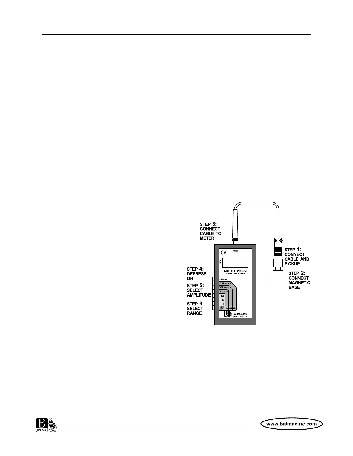
SWITCH PANEL - FUNCTIONS
1. OFF/ON (Grey) - Self-latching button powers
the Model 205 ce on and off.
2. DISP, VEL, ACC (Black) - Self-latching,
vibration amplitude buttons (see Section 4
“Measurements” for a detailed explanation of
the merits of each).
3. RANGE BUTTONS (200, 20, 2, Very Low
Range) (White) - Self-latching Full Scale
Range selector buttons. (205M ce = 2000,
200, 20 VLR).
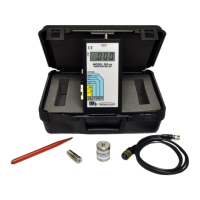
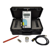
CONNECTIONS - ACCESSORIES
1. Connect the Model 601 Pickup to the Model
059-5' Pickup Cable.
2. Select appropriate mounting accessory (Model
052 Magnetic Base Clamp or Model 051-28
Removable Probe Tip ). Connect to the Model
601 Pickup.
3. Connect cable and pickup assembly to the
Model 205ce.