Install Positive Battery Sense Wire
(REQUIRED FOR REGULATOR OPERATION)
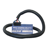
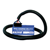
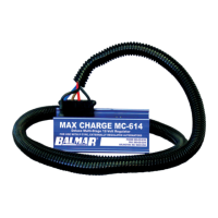
Included with the MC-614 wiring harness kit is a fused wiring pigtail
which features a ring terminal at one end and a butt connector at the
other. In the center is a 1-Amp ATC-type fuse and fuse holder. This
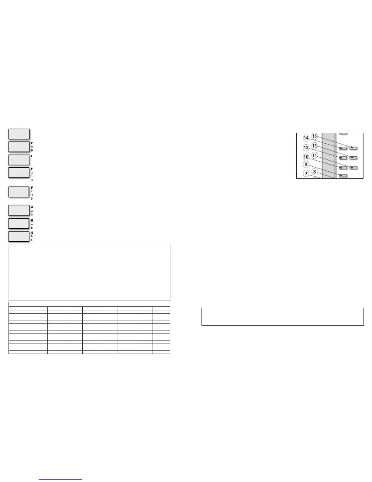
wire MUST be connected at the (#9) Positive Battery Sense terminal.
A female quick connect plug has been pre-attached on the terminal
#9 pin. To complete installation of the sense circuit:
1. Identify the favored location for battery sensing. In most instances,
the positive output of the alternator, the common side of a battery
switch, or the positive post of the battery being charged will work
best. If the batteries are connected to a battery isolator, the
positive sense wire must be connected to the battery side of the
isolator, preferably at the larger of the battery banks.
2. Attach the included wiring pigtail with 1-amp fuse to a length of wire of sufcient to reach the desired sensing location.
If the length of the wire run between the regulator and the sensing location is 8’ or less, a 16-gauge wire is satisfactory.
If the wire run exceeds 8’, increase the wire size to 14 gauge.
3. Remove the female 1/4” spade terminal from the terminal #9 pin. Crimp the spade terminal to the sense wire and
reconnect the spade to the #9 terminal pin.
Install WHITE Stator-In And Tach-Out Wires
When an electric tachometer is used, the alternator’s stator output will provide the electrical pulse needed to drive the
tachometer. The MC-614 has been designed to provide regulated tach output when the WHITE stator wire is connected
to the regulator’s Stator In (#12 in diagram) terminal and the outfeed wire to the electric tachometer is connected to the
Tach Out terminal (#13 in diagram).
Stator output can also be used to detect alternator failure. See Page 6 for details.
When the tachometer is connected via the MC-614, the regulator will ensure that it will not discontinue supplying eld
current when the batteries are fully charged. When connecting the tachometer to the alternator stator output, it will be
necessary to determine the number of poles in the alternator in order to properly adjust your tachometer. Most Balmar
alternators feature 12-pole rotors and stators, though, in some cases, the pole count may be 14. See alternator manual for
specics. See your tachometer manual for adjustment instructions.
Install Battery #2 Temperature Sensor
Your Max Charge MC-614 voltage regulator can accomodate a secondary battery temperature sensor. Used in conjunction
with an optional MC-TS-B battery temperature sensor, the regulator can monitor temperature at a secondary battery bank
and respond to a battery over-temperature condition by discontinuing charging.
To install a secondary battery temperature sensor:
1. Connect the temperature sensor to the secondary battery bank following the directions provided for the primary battery
temperature sensor.
2. Plug the positive and negative sensor to the appropriate positive connector; the BLACK negative sensor wire should
be connected to terminal pin #14. The RED positive sensor wire should be connected to the #15 terminal pin.
Data TX and Data RX
Data TX and RX circuits provide a connection point with outside monitoring equipment. At this time, the Data TX and RX
circuits are only for factory use.
- 5 -
CAUTION: Reversing the polarity of the terminal connections on any of the alternator or battery
temperature sensors can result in invalid sensing and potential damage to alternators, regulator
and/or batteries.
Alternator Temperature Threshold. Controls the setpoint at which point eld current is reduced
when the the alternator temperature sensor indicates an over-temp condition at the alternator. Requires
temperature sensor installation. Preset at 108˚.
Float Voltage. Controls the target voltage for oat stage. Adjustment spans from 13.0 to 13.8 volts.
Default is based on battery program selected. To reverse direction of scroll, release magnet and wait for
LED to display Fv code. Re-activate switch and release when desired value is indicated.
Float Time. Controls time setting for oat mode. Standard value set is 18 minutes. Settings are from 6
minutes to 12 hours. To reverse direction of scroll, release magnet and wait for LED to display F1c code.
Re-activate switch with magnet and release when desired value is indicated.
Low Voltage Limit. Allows user control of the regulator’s low voltage limit.
Field Threshold - Float To Absorption . Controls the criteria used to determine the eld current
threshold required to cycle between absorption and oat charging modes. Factory set at 65%. Raising
“f” increases calculated oat charge time. Adjusted in 1% increments. Span of adjustment is 16% to
96%. To reverse direction of scroll, release “f” code. Reactivate switch with magnet and release when
desired value is indicated.
Field Threshold - Bulk To Absorption . Controls the criteria used to determine eld output re-
quired to maintain calculated bulk charging mode. Factory set at 65% eld output. Raising “fba” shortens
calculated bulk charge time. Lowering “fba” increases calculated bulk charge time. Span of adjustment
is 16% to 96%. To reverse direction of scroll, release magnet and wait for LED to display “fba” code. Re-
activate switch and release when desired value is indicated.
Slope Voltage Correction. Adjusts the voltage (in milivolts) the regulator uses when monitoring
battery temperature sensing. Can be custom adjusted to meet the needs of unique battery technologies.
Consult with battery manufacturer for specic slope voltage recommendations.
Battery Temperature Threshold. Controls the setpoint at which point eld current is discontinued
when the the battery temperature sensor indicates an over-temp condition at batteries being sensed.
Requires temperature sensor installation. Preset at 52°C.
Default Program Settings By Battery Type
UFP FDC GEL AGM OPS FSB HAL
START DELAY (SECS.) 1 1 1 1 1 1 1
SOFT RAMP (SECS.) 60 60 60 60 60 60 60
BULK VOLTAGE 14.1 14.6 14.1 14.38 14.6 14.4 14.0
BULK TIME (MINIMUM) 18 MIN 18 MIN 18 MIN 18 MIN 18 MIN 18 MIN 18 MIN
ABSORPTION VOLTS 13.9 14.4 13.9 14.18 14.4 14.2 13.8
ABSORPTION TIME (MINIMUM) 18 MIN 18 MIN 18 MIN 18 MIN 18 MIN 18 MIN 18 MIN
FLOAT VOLTS 13.4 13.4 13.7 13.4 13.4 13.4 13.5
FLOAT TIME (MINIMUM) 18 MIN 18 MIN 18 MIN 18 MIN 18 MIN 18 MIN 18 MIN
FLOAT TIME (MAXIMUM) 12 HRS. 12 HRS. 12 HRS. 12 HRS. 12 HRS. 12 HRS. 12 HRS.
HIGH VOLTAGE ALARM (VOLTS) 15.2 15.6 15.1 15.38 15.6 15.4 15.0
LOW VOLTAGE ALARM (VOLTS) 12.7 12.7 12.7 12.7 12.7 12.7 12.7
MAX BAT. TEMP. 125˚F/52˚C 125˚F/52˚C 125˚F/52˚C 125˚F/52˚C 125˚F/52˚C 125˚F/52˚C 125˚F/52˚C
MAX ALT. TEMP. 225˚F/107˚C 225˚F/107˚C 225˚F/107˚C 225˚F/107˚C 225˚F/107˚C 225˚F/107˚C 225˚F/107˚C
- 12 -
Fv
.
Fb
.
A
F1
.
c
AL
.
L
FF
.
L
AL
.
1
SL
.
P
B1
.
L
Battery Equalization
Due to the hazardous nature of equalization (the intentional overcharging of batteries to remove sulfation from the battery
plates) we strongly recommend that the process be done at the dock with a voltage-adjustable shorepower charger. If it is
absolutely impossible to do so, equalization can be done with the alternator and regulator by doing the following:
1. In Advanced programming, Pra, change the following values.
2. Cl to a voltage above the desired equalize voltage.
3. AHL to a voltage above the desired equalize voltage.
4. Bv to the desired equalize voltage.
5. Blc to the desired equalize time.
6. Disconnect ALL battery temperature sensors.
7. YOU MUST MONITOR THE BATTERIES DURING EQUALIZE PROCESS!
8. Once the equalization is complete, activate the regulator’s basic programming and reset the battery program mode to UFP, and
allow the program to save. Once saved, access the basic programming mode again and reset for the desired battery program.
WARNING: EQUALIZATION IS A MANUAL PROCESS WITH POTENTIAL DANGERS. DO NOT LEAVE SYSTEM UNATTENDED.
 Loading...