Regulator Display Modes - Short Display/Long Display
The regulator’s three digit alphanumeric LED display provides a scrolling view of charging status. Under normal operation,
the display will indicate the following:
Indicates Balmar.
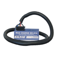
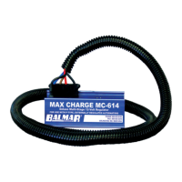
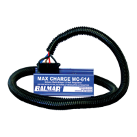
Indicates Model MC-614
Indicates regulator’s default Universal Factory Program. Display will vary based on program selected.
Indicates the regulator’s Belt Load Manager setting. Ranges from b-0 to b-9.
Indicates stage of charge. “b” indicates bulk. “A” indicates absorption. “F” indicates oat.
Indicates system Battery Voltage. Followed by actual voltage reading.
Indicates Calculated voltage (target voltage based on preset program levels). Followed by voltage reading.
Indicates Battery #1 temperature. Followed by NC (not connected), or temperature in celsius.
Indicates Alternator #1 temperature. Followed by NC (not connected), or temperature in celsius.
Indicates Battery #2 temperature. Followed by NC (not connected), or temperature in celsius.
In addition to the information provided in the basic display shown above, the MC-614 long display provides the following
data. The long display is accessed during basic programming, which will be discussed in the next section of the manual.
Indicates the percentage of eld output to the alternator. The higher the percentage, the greater the output.
Indicates regulator’s software revision code.
Indicates temperature setpoint for ambient alternator and battery temperatures. Followed by degrees celsius.
Indicates, in millivolts, the value used to control voltage compensation for battery temperature.
Indicates overall regulator hours. Followed by hours (by tenths) and hours in excess of 100.
Indicates eld threshold from bulk to absorption. Factory set at 65%. Adjust in advanced programming mode.
Indicates eld threshold from oat to absorption. Factory set at 65%. Adjust in advanced programming mode.
Indicates system advisory codes. Individually numbered codes are dened below.
The following advisory codes can be used to determine possible system errors or to identify specic operational modes.
Note that E codes are cumulative and will be held in memory until cleared. Codes can be cleared by entering dSP and
letting it save. Display settings DO NOT need to be changed. See basic programming for more info.
BATTERY #1 TEMP. SENSOR
CABLE SHORTED
BATTERY #1 TEMP. SENSOR
CABLE OPEN OR NOT FOUND
BATTERY #2 TEMP. SENSOR
CABLE SHORTED
BATTERY #2 TEMP. SENSOR
CABLE OPEN OR NOT FOUND
ALTERNATOR #1 TEMP. SENSOR
CABLE SHORTED
ALTERNATOR #1 TEMP. SENSOR
CABLE OPEN OR NOT FOUND
BATTERY #1 TOO HOT. OVER
55˚C. FACTORY DEFAULT
BATTERY #2 TOO HOT. OVER
55˚C. FACTORY DEFAULT
ALTERNATOR TOO HOT. OVER
107˚C
VOLTAGE REGULATOR TOO
HOT. OVER 90˚C
BATTERY VOLTAGE BELOW
12.5 VOLTS
BATTERY VOLTAGE BELOW
10.5 VOLTS
BATTERY #1 TOO HOT. OVER
USER ADJUSTED VALUE
BATTERY #2 TOO HOT. OVER
USER ADJUSTED VALUE
BATTERY VOLTAGE TOO HIGH.
OVER 16 VOLTS
FIELD VOLTAGE TOO HIGH.
STATOR VOLTAGE TOO HIGH.
SMALL ENGINE MODE IS IN
OPERATION
BELT LOAD MANAGER IS IN
OPERATION
- 8 -
BAL
FE
E10 E21 E40
-b-
Hr
E14
E34
E52
UFP
SP
E12
E24 E42
Cv
FFL
E36
614
r3.8
E11
E22 E41
bv
FbA
E15
E20
E35
6-0
SLP
E13
E30
E51
b1
E
AL
b2
Regulator Programming Modes
Using The Magnetic Reed Switch
Control of the MC-614 regulator’s basic and advanced programming
modes is provided by a magnetic reed switch located in the upper left corner
of the regulator’s circuit board. The reed switch provides selectable control of
the regulator’s programming without creating an intrusion point as is common on
many other adjustable voltage regulators currently on the market.
A small screwdriver with a magnet embedded in the tip of the handle is included to
activate the magnetic reed switch. While any magnetic tipped tool can be used, the
Balmar programming screwdriver does an excellent job as an interfacing tool.
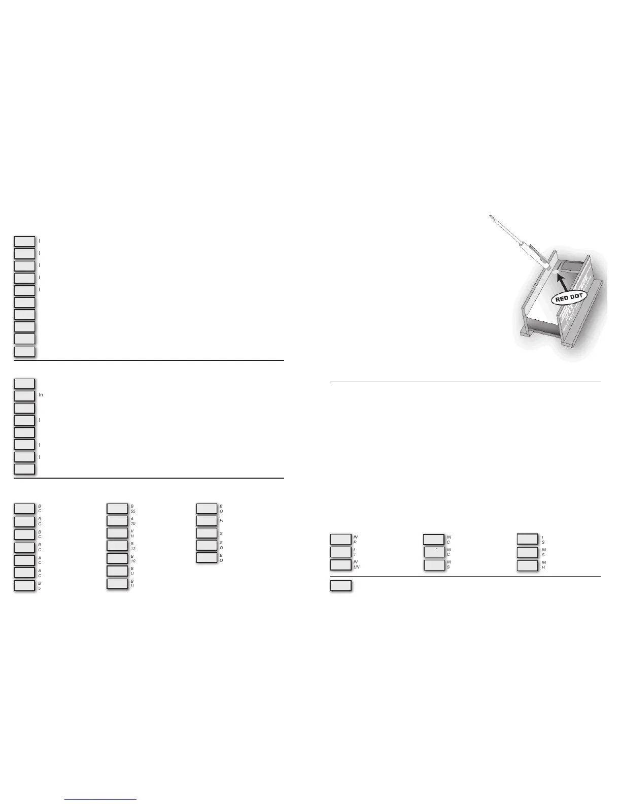
Programming is accomplished by contacting and removing the magnet from the
RED dot afxed to the regulator’s epoxy potting. If the magnet has difculty ac-
tivating the reed switch at that position, try moving the up and down along the
length of the reed switch until the RED light is illuminated at the top of the LED
display, between the second and third display digits. The RED light indicates acti-
vation of the the reed switch.
Within the basic and advanced programming instructions, activation of the reed
switch will be described by the following actions:
• TOUCH / RELEASE - Indicates the action of contacting and immedi-
ately removing the magnet from the reed switch
• TOUCH / HOLD - Indicates the action of contacting and holding the
magnet to the reed switch
• TOUCH / HOLD / RELEASE - Indicates the action of contacting and holding the magnet to the reed switch,
then releasing the reed switch be removing the magnet from the RED dot on the epoxy potting
Basic Programming
Programming For Battery Type
The MC-614 features selectable programs for the following battery technologies; Standard Flooded (FSb), Deep Cycle
Flooded (FdC), gel (gEL), AGM (AgL), Optima (OPS), as well as a factory default program (UFP) and a program for sys-
tems with voltage sensitive halogen equipment (HAL). Programming can be done whenever the regulator is active. Sys-
tem voltage must be greater than 12.5V for programming changes to be saved.
When activating the programming mode, keep in mind that the regulator will scroll through the basic programming mode
three times before saving and returning to the operational mode. To adjust the regulator for your battery type:
1. Turn on the regulator. This may be accomplished by turning the ignition switch at the panel to the ON position. If the
regulator’s BROWN ignition wire is connected to an oil pressure switch, it may be necessary to start the engine to
activate the regulator.
2. Once the regulator is on and the display is scrolling, TOUCH / HOLD the magnetic end of the programming screw-
driver to the RED dot on the regulator as described above.
3. Continue to hold the magnet to the RED dot. The letters PRO will appear on the LED.
4. Continue to hold the magnet to the RED dot. The letters BA will appear on the LED.
5. Continue to hold the magnet to the RED dot. The LED display will begin to scroll through the various battery codes.
6. When the desired battery code is displayed, RELEASE the magnet from the RED dot.
7. The display will indicate BA once again. At this point, you have the option to re-enter the battery type mode by re-
applying the magnet to the RED dot. Otherwise, the display will cycle to bEL, indicating entry into the Belt Load Man-
ager mode.
INDICATES ENTRY INTO BASIC
PROGRAMMING MODE
INDICATES ENTRY INTO BATTERY
TYPE PROGRAM MODE
INDICATES FACTORY DEFAULT
UNIVERSAL FACTORY MODE
INDICATES PROGRAM FOR DEEP
CYCLE FLOODED BATTERIES
INDICATES PROGRAM FOR DEEP
CYCLE GEL BATTERIES
INDICATES PROGRAM FOR AB-
SORBED GLASS MAT BATTERIES
INDICATES PROGRAM FOR
SPIRAL WOUND (OPTIMA)
INDICATES PROGRAM FOR
STD. FLOODED BATTERIES
INDICATES PROGRAM FOR
HALOGEN SYSTEMS
- 9 -
FS
.
B
g
E
.
L
Pr
.
o
HA
.
L
A
g
.
L
bA
.
bE
.
L
OP
.
S
UF
.
P
Fd
.
c
INDICATES ENTRY INTO THE REGULATOR’S BELT LOAD MANAGER MODE.
 Loading...