Design and function
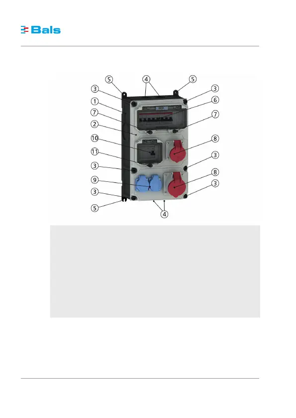
The following figure illustrates the typical design of a VARIABOX.
1 Housing
2 Housing cover
3 Captive housing screws
4 Prepared cable entries
5 Variable fasteners
6 Fuse panel
7 Toggle viewing window (OTC flap), fuse panel
8 CEE socket outlet
9 Domestic socket outlet
10 FI circuit breaker
11 Toggle viewing window (OTC flap), FI circuit breaker
Each VARIABOX consists of the components 1 to 5. All other components vary, depending on the de-
sign, in the quantity and type.
The nameplate on the left side of the housing displays the technical specifications of the VARIABOX,
as illustrated in the figure given below based on an example.
5
Installation and operating manual VARIABOX
(11.2016)
8 / 20