Do you have a question about the baltur BTL 14 and is the answer not in the manual?
Identifies the specific type of burners covered in the manual.
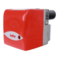
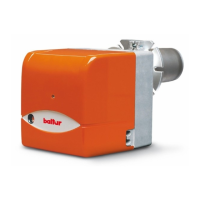
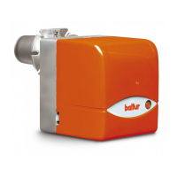
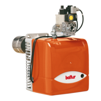
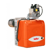
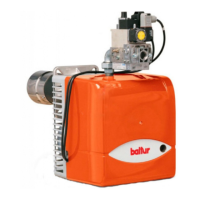
Lists the specific burner models (BTL 14, 20, 26) detailed in the manual.
Provides specific details about the electric diagram, including model compatibility and versioning.
Defines various electrical components (A1, B1, H0, etc.) used in the burner system.
Specifies the color coding convention for electrical wires within the diagrams.
Explains the manual's aim and provides essential general safety instructions for users.
Details the required environmental conditions and maximum duration for equipment storage.
Outlines critical safety precautions to be followed during the installation process.
Lists essential safety guidelines for initial startup, testing, operation, and maintenance phases.
Highlights potential residual risks indicated by pictograms during correct operation.
Details essential electrical safety measures, grounding, and connection precautions.
Presents detailed technical data for BTL 14, 20, and 26 burner models.
Provides NOx and CO emissions data according to EN 267 standards.
Lists the standard accessories provided with the burners for installation.
Details the information presented on the burner's identification plate.
Graphical representation of the operating ranges for different burner models.
Describes automatic control, electrical system rating, and soundproofing.
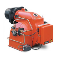
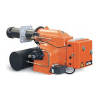
Outlines design elements like combustion head, mounting flange, and component illustration.
Provides detailed measurements and diagrams for burner dimensions across models.
Details the procedure for attaching the flange and gasket for boiler connection.
Explains how to fix the burner to the boiler using supplied hardware.
Illustrates the fan assembly, highlighting key dimensions to respect.
Describes hydraulic connections for gravity fuel supply, including components and pipe sizes.
Details hydraulic connections for a siphon feed system from the tank top.
Explains hydraulic connections for an intake supply system with pipe diameter considerations.
Recommends wire types, power supply checks, and connection practices.
Warns that only qualified personnel should access the burner electrical switchboard.
Explains the burner's automatic startup, fan, ignition, and fuel cut-off sequence.
Describes lock-out conditions, causes, and the procedure to reset the burner.
Outlines initial startup steps and system checks for water and flue dampers.
Explains how to adjust the flame disk and electrode positions for optimal combustion.
Provides specific data for adjusting burner flow rate, air damper, and disk position.
Lists recommended nozzle types for optimal burner performance.
Illustrates correct electrode and disk positioning with specific dimensional data.
Suggests minor electrode adjustments for better ignition performance.
Identifies and lists the individual components of the Suntec fuel pump.
Shows a schematic diagram of the fuel pump's hydraulic circuit.
Explains how to operate the control unit and access diagnostics via the reset button.
Details the meaning of the multi-coloured LED for operational status and diagnostics.
Explains lock-out indication and how to activate diagnostic mode for troubleshooting.
Lists common faults, their causes, and diagnostic indicators (blink codes) with remedies.
Outlines essential maintenance activities like gas analysis, cleaning, and component checks.
Illustrates how to access internal components for cleaning and inspection.
Specifies yearly maintenance for the combustion head and its related parts.
Details maintenance for fuel line components and periodic combustion parameter checks.
Explains how application, maintenance, and environment influence component longevity.
Lists safety components and their expected operational cycles and years of service.
Addresses lock-out with flame on, and no ignition despite fuel spray, listing causes and remedies.
Covers lock-out without fuel spray and burner non-start issues, with causes and solutions.
Details issues like sparks, smoke, soot, and flickering flames, with their causes and remedies.
Addresses internal boiler corrosion and soot at the chimney outlet, providing causes and solutions.
Provides a table correlating GPH, pump pressure, and fuel flow rate for nozzle selection.
Illustrates how to use the flow rate table to determine the correct nozzle for a given capacity.
Provides contact information, website, and email for the manufacturer.
States that catalog information is indicative and subject to manufacturer changes.