6 - 8 Fiveways Boulevard, Keysborough, VIC, Australia 3173
P: 1300 133 944 E: sales@automatictechnology.com.au
W: www.automatictechnology.com.au
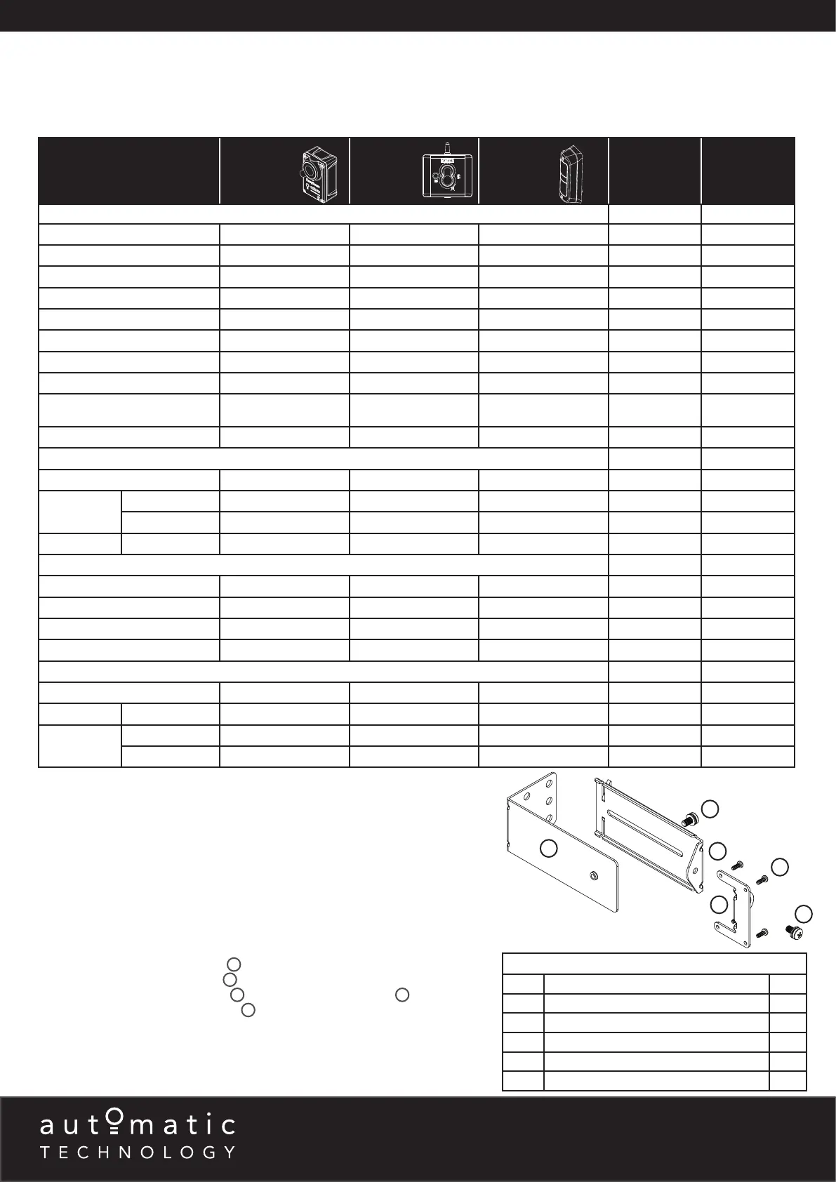
Safety Beam Compatibility
PRODUCT
EASYBEAM WIRELESS PE 2000TS
NO. OF SB
INPUTS
RESISTOR
GARAGE DOOR OPENERS
GDO-6V3
•
x 1 2.2K
GDO-6V4
• •
x 2
GDO-8V3
•
x 1 2.2K
GDO-9V2, GDO-9V3
•
x 1 2.2K
GDO-9V2G2, GDO-9V3G2
• •
x 2
GDO-11V1,
•
x 1 2.2K
RDO-1V3, RDO-1V4
• •
x 2
SDO-2V1, SDO-3V1
•
x 1 2.2K
SDO-2V2, SDO-3V2,
ADVANCE & PRODIGY
• •
x 2
SDO-4V1, GDO-11V3
• •
x 2
LIGHT COMMERCIAL OPENERS
GDO-10V1
•
x 1 5.6K
GDO-10V2
L1 CONSOLE
• • •
x 1 5.6K
L2 CONSOLE
• •
x 3
GDO-10V3L2 L2 CONSOLE
• •
x 3
GATE OPENERS
DCB-05
•
x 1 5.6K
DCB-05V2
• • •
x 2 5.6K
NEOSLIDER NES24
•
x 1 5.6K
NEOSLIDER V2, NEOSLIDER V3
• • •
x 2 5.6K
INDUSTRIAL OPENERS
AXESS 1101
•
x 1 5.6K
AXESS 1505 L2 CONSOLE
• •
x 3
AXESS 3000
PRO SERIES
L1 CONSOLE
• • •
x 1 5.6K
L2 CONSOLE
• •
x 3
Safety Beams (SB) extend across the opening. The Safety Beam is designed to detect an obstruction while the door / gate is closing
and to send a signal to the opener to reverse or stop the door / gate movement. There are three (3) different types of Safety Beam
Kits available and they are not compatible with all products. Please refer to table below for product and Safety Beam compatibility.
Mounting Brackets
All three (3) types of Safety Beam Kits use the same mounting brackets.
MOUNTING KIT
ITEM DESCRIPTION QTY
1 PE 2000TS BRACKET 2
2 ADJUSTMENT BRACKET 2
3 MOUNTING BRACKET 2
4 TAPTITE SCREW “B” PH M3 X 5 ZNC 8
5 PAN HEAD SCREW W/WASHER M5 X 10 4
Mounting Kit for all Safety Beams
4
1
5
2
3
5
Right side
bracket
NOTE: Mount the receiver on the side of the doorway / gateway closest to the
opener / console.
Assembling the Mounting Bracket
a. Attach the PE 2000TS Bracket
1
to the Safety Beam Transmitter (TX) using
four (4) M3 x 5 Taptite screws
4
.
b. Connect the mounting bracket
3
to the adjustment bracket
2
with two (2)
of the M5 x 10 Pan Head Screws
5
.
c. Repeat steps (a) and (b) to assemble the Safety Beam Receiver (RX).
d. Mount the receiver on the side of the doorway / gateway closest to the
opener / console and the transmitter on the other side in line with the receiver.
The mounting surface should be rigid. Affix with a minimum of four (4) screws
(not supplied).
 Loading...