P. 10 - Inputs
Inputs
opto
Red LED
inv
-
+
ground
Schmitt-input
1 K
Aircoil
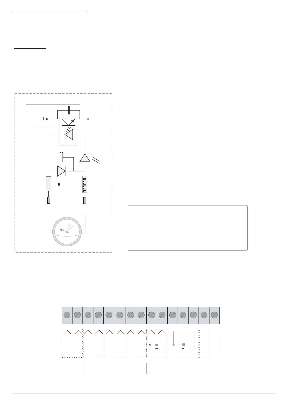
Scematic display of an input
All inputs are equipped with opto-couplers, which provide a perfect separation between
the internal BANDIT electronics and the “outside world”. This way, all unwanted disturbing
signals, caused by lightning, induction or R.F. tensions, are kept outside.
The device, model 240DB , is equipped with 3 inputs. Unlike other Bandit models, where every
in- and output is free adjustable, in this 240DB model, the function of each input is fixed through
hardware settings in the PCB structure.
You’ll find a detailed description of each input function on the following pages.
Electrical properties of an input:
- polarised (+ and - signs beneath connectors on
PCB.
- secured for possible polarity reverse and equipped
with RC- and LC- filter.
- an input has to be stable for at least 0.2 seconds
before the new situation is accepted.
- the connected voltage can be either from an external
source or from the 12 V BANDIT supply source
itself [Supply].
- the input current with 12 V is ~ 10 mA each input.
- each input is equipped with a schmitt-input, after
the opto-coupler. The trigger voltage is approximately
6 V with hysteresis of + and - 1V. This way,
unreliable input voltages are being avoided
as much as possible.
1
1
5
1
5
1
V =
COM
OKout
Grdout
Alout
Tmpout
Alin
Panin
Grdin
Supply
12 V
500 mA
Ta
P+
A+
G+
+
Tb
P-
A-
G-
-
After adjustments: check the voltage over
the inputs.
- Consider < 2 V as no volts.
- Consider > 9 V as 12 V .
Voltages between 2 and 9 V are not normal
and will cause problems sooner or later.
12 VDC
Supply
3 x inputs 4 x outputs
BANDIT 240 DB v.206
npn npn


 To Next Page