Do you have a question about the B&R Industries Provit 5000 and is the answer not in the manual?
Tracks revisions, new features, and changes to the Provit 5000 manual and product line.
Provides guidance on manual usage, legends, and chapter overviews.
Explains symbols and attention marks used in the manual for safety and clarity.
Briefly describes the content and purpose of each chapter in the manual.
Defines abbreviations and technical terms used throughout the document.
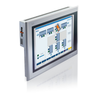
Introduces Provit 5000 Industrial PCs, their design, architecture, and operating systems.
Lists IPC components and notes that accessories are ordered separately.
Details model numbers for bus units, system units, and processors.
Lists model numbers and descriptions for controller bus units with various slot configurations.
Lists model numbers and technical data for system units with different chipsets and memory slots.
Details model numbers and descriptions for processors compatible with Provit 5000.
Lists model numbers and descriptions for hard disks and PC Card Flash memory.
Details technical data for SIMM and DIMM memory modules.
Lists technical data for interface boards like COM, CAN, Ethernet, and PC Card slots.
Lists model numbers and technical data for various Provit 5000 display units.
Lists model numbers and descriptions for display kits, including display and cable.
Lists model numbers and descriptions for optional accessories.
Lists model numbers and descriptions for software packages and drivers.
Lists model numbers and descriptions for user manuals and documentation.
Provides general technical specifications for controllers, including compatibility, standards, and protection.
Details technical specifications for IPC5000, IPC5600, IPC5000C, and IPC5600C controllers.
Lists technical data for IPC5000 and IPC5600 bus units, including slots, voltage, and fans.
Details technical data for IPC5000 and IPC5000C bus units.
Details technical data for IPC5600 and IPC5600C bus units.
Provides technical data for IPC5000 and IPC5600 system units with Socket 7.
Provides technical data for IPC5000 and IPC5600 system units.
Provides technical data for IPC5000C and IPC5600C system units.
Lists technical data for processors used in IPC5000/IPC5600 and IPC5000C/IPC5600C.
Lists technical data for IPC5000 and IPC5600 processors.
Lists technical data for IPC5000C and IPC5600C processors.
Provides technical data for hard disk drives from 1.44 GB to 6 GB.
Lists technical data for silicon disks such as PC Cards and Compact Flash.
Details technical data for SIMM and DIMM memory modules.
Details technical data for IPC5000 and IPC5600 main memory.
Details technical data for IPC5000C and IPC5600C main memory.
Lists technical data for interface boards like COM, CAN, Ethernet, and PC Card slots.
Lists technical data for Arcnet interface boards.
Provides dimensional drawings for various IPC5000 and IPC5600 models.
Shows dimensional drawings for the 2-slot IPC5000 and IPC5000C.
Shows dimensional drawings for the 4-slot IPC5000 and IPC5000C.
Shows dimensional drawings for the 5-slot IPC5000 and IPC5000C.
Shows dimensional drawings for the 4-slot IPC5600 and IPC5600C.
Shows dimensional drawings for the 5-slot IPC5000 and IPC5600C.
Shows dimensional drawings for the 6-slot IPC5000 and IPC5600C.
Provides guidelines for mounting controllers, including standard and remote options.
Specifies operating temperature ranges for IPC5000, IPC5600, IPC5000C, and IPC5600C models.
Details operating temperature ranges for IPC5000/IPC5600 with Intel Pentium and AMD K6 processors.
Details operating temperature ranges for IPC5000C with Celeron and Pentium III processors.
Details operating temperature ranges for IPC5600C with Celeron and Pentium III processors.
Illustrates and labels components on IPC5000 and IPC5600 bus units.
Shows an illustration of IPC5000 components for the 2-slot bus unit.
Shows an illustration of IPC5000 components for the 4-slot bus unit.
Shows an illustration of IPC5600 components for the 4-slot bus unit.
Shows an illustration of IPC5600 components for the 6-slot bus unit.
Shows an illustration of IPC5000C components for the 2-slot bus unit.
Shows an illustration of IPC5000C components for the 4-slot bus unit.
Shows an illustration of IPC5600C components for the 4-slot bus unit.
Shows an illustration of IPC5600C components for the 6-slot bus unit.
Details drive options for Provit 5600 IPC units and lists drive types.
Provides mounting guidelines and technical data for the 5A5600.01 controller (Floppy Disk Drive).
Provides mounting guidelines and technical data for the 5A5600.02 controller (CD-ROM drive).
Provides technical data for the 5A5600.03 controller (Panel FDD).
Provides mounting guidelines and technical data for the 5A5600.04 controller (LS-120/CD-ROM).
Provides mounting methods and technical data for the 5A5600.05 controller (FDD/DVD-ROM).
Provides mounting methods and technical data for the 5A5600.07 controller (FDD CD-RW).
Details general information and technical data for system units with Socket 7.
Provides general information on system units referring to specific models.
Lists technical data for system units with Socket 7, covering mainboard, BIOS, chipset, and DRAM.
Describes the functions implemented on the mainboard, such as processor socket and I/O controller.
Lists compatible processors and explains jumper settings for clock frequency and power supply.
Explains jumper settings for system units 5C5002.02, 5C5001.03, and 5C5601.01.
Describes DRAM socket specifications and refers to Main Memory section for details.
Details the pin assignment and standard settings for COM1 and COM2 serial interfaces.
Explains pin assignments and standard settings for the LPT1 parallel interface.
Describes the pin assignment and standard settings for the external floppy disk drive interface.
Mentions the availability of USB host controllers and ports on Provit 5000 system units.
Details pin assignments and standard settings for connecting an AT keyboard via PS/2.
Details pin assignments and standard settings for connecting a PS/2 mouse.
Provides technical data for the integrated VGA controller and its connections.
Explains how to connect a Provit 5000 flat display to the Panellink interface.
Explains how to connect an external monitor to the CRT interface.
Discusses the possibility and limitations of using an external graphic card.
Explains the relationship between video memory, resolution, and the number of colors supported.
Describes the fuse location and specifications for power supply voltage.
Explains the functions of the status LEDs on the IPC 5000 and 5600 controllers.
Describes the lithium battery, its compartment, and lifespan for CMOS memory.
Explains the location and activation method for the reset button.
Details the function and settings of the recovery and user jumpers.
Explains the recovery mode and its activation via jumper settings.
Describes the user jumper's purpose and its utilization with Provit 5000 Utilities.
Explains the MTC system and its responsibilities for additional functions.
Describes keyboard operation by MTC and its hot-plug capability.
Explains MTC handling of Panelware modules and daisy-chaining.
Details how to read statistical operating data using the MTC.
Explains how the MTC monitors temperature and regulates fan speed.
Explains how the MTC can evaluate the CMOS battery status.
Provides general information and technical data for system units with Socket 370.
Lists system units covered in this section and refers to further details.
Lists technical data for system units with Socket 7, covering mainboard, BIOS, chipset, and DRAM.
Describes the functions implemented on the mainboard, such as processor socket and I/O controller.
Lists compatible processors and explains warranty implications for non-B&R processors.
States that no jumper settings are required for system units with Socket 370.
Describes DRAM socket specifications and refers to Main Memory section for details.
Details pin assignment and standard settings for COM1 and COM2 serial interfaces.
Explains pin assignments and standard settings for the LPT1 parallel interface.
Describes the pin assignment and standard settings for the external floppy disk drive interface.
Mentions the availability of USB host controllers and ports on Provit 5000 system units.
Details pin assignments and standard settings for connecting an AT keyboard via PS/2.
Details pin assignments and standard settings for connecting a PS/2 mouse.
Provides technical data for the integrated VGA controller and its connections.
Explains how to connect a Provit 5000 flat display to the Panellink interface.
Explains how to connect an external monitor to the CRT interface.
Discusses the possibility and limitations of using an external graphic card.
Explains the relationship between video memory, resolution, and the number of colors supported.
Describes the fuse location and specifications for power supply voltage.
Details the location and addressability of the Hardware Security Key.
Explains the functions of the status LEDs on the IPC 5000C and 5600C controllers.
Describes the lithium battery, its compartment, and lifespan for CMOS memory.
Explains the location and activation method for the reset button.
Details the function of the DIP switch settings for boot block and recovery mode.
Explains how to use DIP switch 1 to control the Boot Block write protect.
States that the user jumper is not required for system functions and can be used with Provit 5000 Utilities.
Explains the MTC system and its responsibilities for additional functions.
Describes keyboard operation by MTC and its hot-plug capability.
Explains MTC handling of Panelware modules and daisy-chaining.
Details how to read statistical operating data using the MTC.
Explains how the MTC monitors temperature and regulates fan speed.
Provides technical data and configuration for the onboard Ethernet controller.
Provides an overview and visual examples of various Provit keypad modules.
Lists the available Provit 5000 display kit types and their descriptions.
Provides guidelines for mounting display kits, including remote operation and fasteners.
Specifies standard and maximum distances for remote display operation based on revision numbers.
Refers to Chapter 3 for Panelware module usage with display units.
Explains how to adjust brightness and contrast for Provit display units.
Explains the relationship between video memory, resolution, and the number of colors supported.
Illustrates the block diagram showing the connection between controller, display, and peripherals.
Details the photo, dimensions, and technical data for the 5D5100.01 and 5D5100.04 display units.
Shows photographs of the 5D5100.01 and 5D5100.04 display units.
Shows dimensional drawings for the 5D5100.01 and 5D5100.04 display units.
Lists technical data for the 5D5100.01 and 5D5100.04 display units.
Provides measurements for cutout and drill holes for door installation of display units.
Explains mounting guidelines for display units on controller units.
Details the photo, dimensions, and technical data for the 5D5200.01 and 5D5210.01 display units.
Shows photographs of the 5D5200.01 and 5D5210.01 display units.
Shows dimensional drawings for the 5D5200.01 and 5D5210.01 display units.
Lists technical data for the 5D5200.01 and 5D5210.01 display units.
Provides measurements for cutout and drill holes for door installation of display units.
Explains mounting guidelines for display units on controller units.
Details the photo, dimensions, and technical data for the 5D5200.04 display unit.
Shows a photograph of the 5D5200.04 display unit.
Shows dimensional drawings for the 5D5200.04 display unit.
Lists technical data for the 5D5200.04 display unit.
Provides measurements for cutout and drill holes for door installation of the 5D5200.04 unit.
Explains mounting guidelines for the 5D5200.04 display unit on a controller.
Details the photo, dimensions, and technical data for the 5D5201.02 and 5D5211.02 display units.
Shows photographs of the 5D5201.02 and 5D5211.02 display units.
Shows dimensional drawings for the 5D5201.02 and 5D5211.02 display units.
Lists technical data for the 5D5201.02 and 5D5211.02 display units.
Provides measurements for cutout and drill holes for door installation of display units.
Explains mounting guidelines for display units on controller units.
Details the photo, dimensions, and technical data for the 5D5201.03 and 5D5211.03 display units.
Shows photographs of the 5D5201.03 and 5D5211.03 display units.
Shows dimensional drawings for the 5D5201.03 and 5D5211.03 display units.
Lists technical data for the 5D5201.03 and 5D5211.03 display units.
Provides measurements for cutout and drill holes for door installation of display units.
Explains mounting guidelines for display units on controller units.
Details the photo, dimensions, and technical data for the 5D5211.06 display unit.
Shows a photograph of the 5D5211.06 display unit.
Shows dimensional drawings for the 5D5211.06 display unit.
Lists technical data for the 5D5211.06 display unit.
Provides measurements for door installation of the 5D5211.06 display unit.
Details the photo, dimensions, and technical data for the 5D5202.01, 5D5202.03, and 5D5212.01 units.
Shows photographs of the 5D5202.01, 5D5202.03, and 5D5212.01 display units.
Shows dimensional drawings for the 5D5202.01, 5D5202.03, and 5D5212.01 units.
Lists technical data for the 5D5202.01, 5D5202.03, and 5D5212.01 display units.
Provides measurements for door installation of the 5D5202.01, 5D5202.03, and 5D5212.01 units.
Details the photo, dimensions, and technical data for the 5D5212.02 display unit.
Shows a photograph of the 5D5212.02 display unit.
Shows dimensional drawings for the 5D5212.02 display unit.
Lists technical data for the 5D5212.02 display unit.
Provides measurements for door installation of the 5D5212.02 display unit.
Explains mounting guidelines for the 5D5212.02 display unit on a controller.
Details the photo, dimensions, and technical data for the 5D5212.04 display unit.
Shows a photograph of the 5D5212.04 display unit.
Shows dimensional drawings for the 5D5212.04 display unit.
Lists technical data for the 5D5212.04 display unit.
Explains mounting guidelines for the 5D5212.04 display unit on a swing arm system.
Details the photo, dimensions, and technical data for the 5D5213.01 display unit.
Shows a photograph of the 5D5213.01 display unit.
Shows dimensional drawings for the 5D5213.01 display unit.
Lists technical data for the 5D5213.01 display unit.
Provides measurements for door installation of the 5D5213.01 display unit.
Explains mounting guidelines for the 5D5213.01 display unit on a controller.
Details the photo, dimensions, and technical data for the 5D9200.01 display unit.
Shows a photograph of the 5D9200.01 display unit.
Shows dimensional drawings for the 5D9200.01 display unit.
Lists technical data for the 5D9200.01 display unit.
Provides measurements for door installation of the 5D9200.01 display unit.
Explains mounting guidelines for the 5D9200.01 display unit on a controller.
Details the photo, dimensions, and technical data for the 5D55xx.xx series displays.
Shows photographs of the 5D55xx.xx series displays.
Shows dimensional drawings for the 5D55xx.xx series displays.
Lists technical data for the 5D55xx.xx series displays.
Provides measurements for door installation of the 5D55xx.xx series displays.
Explains mounting guidelines for the 5D55xx.xx series displays on controllers.
Describes how to label keys on display units using legend strips.
Illustrates key labels for 5D5500.10 and 5D5500.32 display units.
Illustrates key labels for 5D5501.01 and 5D5510.10 display units.
Details the photo, dimensions, and technical data for the 5D5600.0x and 5D5601.0x display units.
Shows photographs of the 5D5600.0x and 5D5601.0x display units.
Shows dimensional drawings for the 5D5600.0x and 5D5601.0x display units.
Lists technical data for the 5D5600.0x and 5D5601.0x display units.
Provides measurements for door installation of the 5D5600.0x and 5D5601.0x units.
Explains mounting guidelines for the 5D5600.0x and 5D5601.0x display units.
Describes the configuration and evaluation of keys and LEDs on the display units.
Explains the location and activation method for the reset button on the display unit.
Explains the functions of the four status LEDs on the display unit.
Describes how to label keys on display units using legend strips.
Lists order data for accessories related to 5D5600.0x and 5D5601.0x units.
Introduces display kits, their purpose, and components.
Lists the available Provit 5000 display kit types and their descriptions.
Provides guidelines for mounting display kits, including remote operation and fasteners.
Refers to Chapter 3 for Panelware module usage with display units.
Details the photo, dimensions, and technical data for the 5D5000.03 display kit.
Shows a photograph of the 5D5000.03 display kit.
Shows dimensional drawings for the 5D5000.03 display kit.
Lists technical data for the 5D5000.03 display kit.
Details the photo, dimensions, and technical data for the 5D5000.10 display kit.
Shows a photograph of the 5D5000.10 display kit.
Shows dimensional drawings for the 5D5000.10 display kit.
Lists technical data for the 5D5000.10 display kit.
Details the photo, dimensions, and technical data for the 5D5000.14 display kit.
Shows a photograph of the 5D5000.14 display kit.
Shows dimensional drawings for the 5D5000.14 display kit.
Lists technical data for the 5D5000.14 display kit.
Details the photo, dimensions, and technical data for the 5D5000.18 display kit.
Shows a photograph of the 5D5000.18 display kit.
Shows dimensional drawings for the 5D5000.18 display kit.
Lists technical data for the 5D5000.18 display kit.
Provides an overview and visual examples of various Provit keypad modules.
Provides general information and dimensions for standard and special keypad modules.
Shows dimensional drawings for standard and special keypad modules.
Divides keypad modules into standard and special groups, explaining connectivity.
Explains how to connect standard keypad modules to controllers or other modules.
Details connection of standard keypad modules using cables and sockets.
Provides dimensions and technical data for the 16-key keypad module.
Provides dimensions and technical data for the 12+4 key keypad module.
Provides dimensions and technical data for the 8-key keypad module.
Provides dimensions and technical data for the 4-key keypad module.
Describes special keypad modules, including dummy modules and E-stop buttons.
Provides dimensions and technical data for the dummy keypad module.
Provides dimensions and technical data for the E-stop button keypad module.
Provides dimensions and technical data for the key switch keypad module.
Provides dimensions and technical data for the START/STOP switch keypad module.
Describes key legend sheets and their order data.
Lists accessories delivered with each keypad module.
Introduces BIOS, its function, and the EliteBIOS used on Provit IPCs.
Explains how to enter the BIOS Setup utility and the POST process.
Lists and describes the keys used for navigating within the BIOS Setup utility.
Addresses booting issues after BIOS changes and how to override settings.
Describes the BIOS system for Socket 7 units, recommending B&R setup defaults.
Shows the BIOS Setup main menu and explains access method.
Explains date, time, and hard disk settings in Standard CMOS Setup.
Details BIOS features like Virus Warning, CPU Cache, and Boot Sequence.
Provides chipset-specific setup options for advanced users.
Explains power saving options and their configurations for Doze, Standby, Suspend, and HDD Power Down.
Details settings for Plug and Play and PCI devices, including resource allocation.
Explains loading factory default settings for stable system operations.
Explains loading factory settings for optimal IPC performance.
Describes settings for integrated peripherals like IDE, USB, and serial ports.
Explains setting or disabling the system password.
Describes automatic detection and configuration of IDE devices.
Explains how to save BIOS Setup changes and exit.
Explains how to exit BIOS Setup without saving changes.
Covers B&R specific settings for integrated peripheral devices.
Compares BIOS and Setup defaults across different Elite BIOS versions.
Compares BIOS and Setup defaults for BIOS Features across versions.
Compares BIOS and Setup defaults for Chipset Features across versions.
Compares BIOS and Setup defaults for Power Management across versions.
Compares BIOS and Setup defaults for PNP/PCI Configuration across versions.
Compares BIOS and Setup defaults for Integrated Peripherals across versions.
Compares BIOS and Setup defaults for Additional Peripherals across versions.
Describes the BIOS system for Socket 370 units, recommending B&R setup defaults.
Shows the BIOS Setup main menu and explains access method.
Explains date, time, and hard disk settings in Standard CMOS Setup.
Details BIOS features like Virus Warning, CPU Cache, and Boot Sequence.
Provides chipset-specific setup options for advanced users.
Explains power saving options and their configurations for Doze, Standby, Suspend, and HDD Power Down.
Details settings for Plug and Play and PCI devices, including resource allocation.
Explains loading factory default settings for stable system operations.
Explains loading factory settings for optimal IPC performance.
Describes settings for integrated peripherals like IDE, USB, and serial ports.
Covers B&R specific settings for integrated peripheral devices.
Explains setting or disabling the system password.
Describes automatic detection and configuration of IDE devices.
Explains how to save BIOS Setup changes and exit.
Explains how to exit BIOS Setup without saving changes.
Compares BIOS and Setup defaults across different Elite BIOS versions.
Compares BIOS and Setup defaults for BIOS Features across versions.
Compares BIOS and Setup defaults for Chipset Features across versions.
Compares BIOS and Setup defaults for Power Management across versions.
Compares BIOS and Setup defaults for PNP/PCI Configuration across versions.
Compares BIOS and Setup defaults for Integrated Peripherals across versions.
Compares BIOS and Setup defaults for Additional Peripherals across versions.
Explains how to upgrade the BIOS using a diskette or CD-ROM.
Guides through using the BIOS Upgrade Utility Main Menu and its functions.
Explains how to perform BIOS upgrades acoustically via PC speaker.
Lists status messages and their meanings during BIOS upgrades.
Lists general messages and necessary user actions during upgrades.
Lists acoustic error messages and their potential causes.
Lists alarm signal codes from Award BIOS during boot-up errors.
Introduces Provit 5000 Utilities and its components, focusing on MTC Function Libraries.
Details the necessary libraries for MTC service and safety functions.
Shows a block diagram illustrating the MTC function libraries design.
Explains how to use the MTC Diagnose tool for system analysis.
Details RAM address assignments, DMA channel assignments, and I/O address assignments.
Lists RAM address assignments and their corresponding resources.
Lists DMA channel assignments and their corresponding resources.
Illustrates Upper Memory Area assignments in RAM.
Lists I/O addresses and their corresponding resources.
Shows interrupt assignments for various system components.
Provides general info, pin assignment, status LEDs, and jumper settings for the RS232 interface board.
Describes the RS232 interface board's compatibility and configuration options.
Details the pin assignment for the RS232 interface.
Explains the status LEDs for transmit, receive, and handshake lines.
Outlines jumper settings for interface description and IRQ allocation.
Explains how to set the interface description for COM ports using jumpers.
Details IRQ number assignments for both interfaces using jumper rows.
Provides examples of IRQ setting configurations for COM ports.
Covers general info, photo, connection, technical data, installation, and order data for the external floppy disk drive.
Introduces the external FDD and its connection to Provit IPCs.
Shows a photograph of the external floppy disk drive.
Explains the connection method using a Centronics cable and its maximum length.
Lists technical data for the external disk drive, including format, dimensions, and power consumption.
Describes how to integrate the disk drive into a housing or use an installation plate.
Lists model numbers and descriptions for external floppy disk drives and related accessories.
Covers general information, photo, power supply, and order data for the external CD-ROM drive.
Explains the use of an SCSI adapter for operating the external CD-ROM drive.
Shows a photograph of the external CD-ROM drive.
Details the power supply requirements for the CD-ROM drive.
Lists model numbers and descriptions for the external CD-ROM drive and SCSI adapter.
Covers dimensions, mounting instructions, mounting methods, technical data, and accessories for the remote drive.
Shows dimensional drawings for the remote CD ROM / LS-120 drive.
Provides instructions for mounting the drive vertically or horizontally.
Explains two different methods for mounting the remote CD-ROM/LS-120 drive.
Describes table mounting using rubber feet for standard devices.
Explains mounting with a front cover, noting it must be ordered separately.
Lists technical data for the remote CD ROM / LS-120 drive.
Mentions the availability of a front cover for mounting the drive.
Details model numbers and mounting instructions for the add-on CD ROM drive.
Provides mounting guidelines for the add-on CD ROM with the controller.
Lists technical data for the add-on CD ROM drive.
Describes the parallel adapter for Dallas Hardware Security Keys and its features.
Details the IBM compatible AT enhanced keyboard, its connection, and layout availability.
Lists technical data and pin assignments for remote display cables.
Describes the panel flange adapter for the 5D5212.04 display unit and its order data.
Explains the function of the hardware security key for software protection.
Provides technical data for the lithium battery, including lifespan, capacity, and storage.
Covers general information about CAN Bus, its features, and B&R's support.
Defines CAN and lists its key features.
Explains how bus length is determined by cable type, transfer speed, and nodes.
Details CAN interface chip, interrupt, I/O address, and data area access.
Provides technical data and pin assignments for the Elo Accu Touch screen.
Lists chemicals to which the décor foil is resistant according to DIN 42 115.
Lists chemicals with which the décor foil shows resistance.
Provides technical data for 2.1 GB and 4.3 GB hard disks.
Lists technical specifications for 2.1 GB and 4.3 GB hard disks.
Lists technical specifications for 6 GB hard disks.
Provides MTBF and operating time specifications for hard disks.
Describes user-serviceable maintenance tasks for mainboard and interface boards.
Explains how to remove the housing cover to access the battery or fuse.
Covers maintenance for the mainboard, including CMOS battery and fuse replacement.
Details how to change the CMOS battery using lithium batteries.
Explains how to change the fuse to protect controllers from overloading.
Describes maintenance for the interface board, specifically the SRAM battery.
Explains how to change the SRAM battery, referencing Lithium Battery technical data.
Provides definitions for technical terms used in the manual.
| Brand | B&R Industries |
|---|---|
| Model | Provit 5000 |
| Category | Desktop |
| Language | English |