Do you have a question about the B&R PLC PP15 and is the answer not in the manual?
Explains the PP15 concept for monitoring and control of d&b sound systems, including emergency purposes.
Lists device and channel error codes for D12, D6, and E-PAC amplifiers.
Details the PP15 control panel (display, keys) and external controls.
Details power supply, CAN, and RS232 data port pin assignments for the PP15.
Explains the 16 software-configurable digital inputs for triggering functions and remote control.
Details the 6 digital outputs used for system status display and driving external devices.
The B&R PLC PP15 is a Programmable Logic Controller designed for use with the d&b Remote network, enabling reliable monitoring and control of d&b sound reinforcement systems. This device simplifies complex operations, making it accessible without requiring in-depth technical knowledge. Its primary function is to monitor and control up to 255 d&b amplifiers via the d&b remote network, which is particularly crucial for systems used in accordance with IEC 60849 'Sound Systems for Emergency Purposes'.
The PP15 allows for comprehensive remote control of d&b amplifiers by recalling dedicated presets. This includes managing various amplifier parameters such as AmpPresets, Standby mode, and Mute functions. Users can precisely control level settings from -57.5 dB to +6 dB with 0.5 dB detents, activate or deactivate delay settings, and configure filters (CUT, HFA, etc.) and equalizer functions. Additionally, it supports locking "Secondary Masters," such as a PC running R1 Remote control software, to prevent unauthorized changes.
A key feature of the PP15 is its error monitoring capability. The device cyclically polls all registered amplifiers for errors. If an error is detected in any device, it is displayed on the PP15's error page with a specific error number. A general error message is also indicated at the "Error" digital output. The system can provide a plain text description of the error upon request. In cases where an amplifier fails to respond to periodic polls, a "PWR/Comm. Loss" error is displayed and signaled through the "Error" digital output, indicating a communication breakdown or power loss. The manual provides a detailed list of device and channel error numbers for D12, D6, and E-PAC amplifiers, helping users diagnose issues ranging from system and program errors to power supply overtemperature, overvoltage, undervoltage, and speaker faults.
The PP15 is equipped with 16 software-configurable digital inputs (DI) that allow different functions to be triggered. Inputs DI 1-DI 10 can function as push buttons, mirroring the 0-9 keys on the front panel for remote preset control. Alternatively, DI 1-DI 12 can be configured as switches for zone call functions, where the assigned preset remains active as long as the switch is closed. Input DI 15 (Poll on/off) can disable continuous monitoring of connected amplifiers, useful when amplifiers are temporarily disconnected. Input DI 16 is designated for the alarm contact, holding the highest priority.
The device also features 6 digital outputs (DO) to display system status or drive external devices. DO 12 (Poll) indicates when connected amplifiers are being checked for faults, while DO 13 (Ready) signals that the PP15 is initialized and operational. DO 14 (Alarm) indicates an alarm signal applied to input DI 16. An error message from a controlled amplifier triggers DO 16 (Error) and causes DO 15 (Buzzer) to emit periodic impulses (0.5 s high, 4.5 s low). The buzzer can be reset via the PP15 menu, but a new fault will reactivate it.
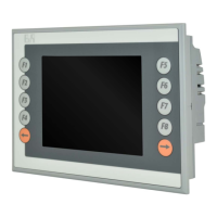
The PP15 offers a user-friendly interface with an LC Display [1] that acts as the primary visual feedback for all errors and menu pages. Function keys [2] allow users to navigate between different menu pages, guided by on-screen prompts. Up/Down keys [3] facilitate selecting menu items and browsing through error messages. The Enter key [4] confirms menu selections and requests detailed error causes. Preset keys with LED displays [5] allow for quick recall of amplifier settings (Presets) assigned to specific keys. An LED lights up when a key is selected, and all LEDs flash in case of an alarm.
The display provides clear information, starting with a "Start page" showing the current preset, a text description, and the number of reported errors. Pressing F2 leads to an "Error page" with detailed error descriptions. If more than three errors are present, users can scroll through them using the Up/Down keys. Error messages include the dbCAN-ID of the reporting amplifier (subnetwork and device ID) or a device name. For "Error xx" messages, pressing the Enter key provides a detailed description from the amplifier. "PWR/Comm. loss" indicates communication failure, possibly due to a faulty amplifier, disconnection from mains, or an interrupted network connection.
The PP15 includes several extended functions accessible via the F3 key, which are crucial for system maintenance and troubleshooting. The "Reset Buzzer" function temporarily acknowledges an error and switches off the buzzer, though a new error will reactivate it. The "Support Hotline" option allows for storing a contact and telephone number for service. The "Battery State" function reports the condition of the PP15's internal battery. If a "> Change Battery" message appears, it signals a need to contact the Service department, as an empty battery can lead to data loss. This is an important maintenance item that should be part of regular service routines. The "Reset Power Panel" function performs a restart of the PP15.
Uploading the d&b software routines to the PP15 is a straightforward process. It requires a computer with a serial COM port (RS 232) and a serial cross cable (null modem cable). Users adjust two hex switches on the PP15's rear panel, connect the PP15 to the computer, and then run the "Start.bat" file from the extracted d&b software routines. The PVI Transfer software then displays the upload script.
For configuration, the PP15 uses a CAN-Bus connection to a PC running the PPTool program. This allows for registering amplifiers (dbCAN-ID) and storing presets assigned to keys or inputs. The PC needs a CAN interface (R60/R70) and can be connected regardless of whether amplifiers are present.
The PP15 also supports monitoring according to IEC 60849, ensuring the sound reinforcement system's loudspeakers (Load monitoring) and incoming signals (Input monitoring) are continuously checked by the d&b amplifiers. The PP15 displays these error messages centrally. Due to amplifier boot and power-up times, the PP15's power must be backed up by a UPS to ensure constant operational readiness. The internal error logbook is limited to 50 entries, and the "AutoReset" digital output indicates when the PP15 has been automatically reset and restarted, providing a clear signal for system events.
| Display Type | TFT LCD |
|---|---|
| Processor | Intel Atom |
| Power Supply | 24 VDC |
| Model | PP15 |
| Display Size | 15 inch |
| Touchscreen | Yes |
| Interfaces | Ethernet, USB, Serial |
| USB Ports | 2 |
| Ethernet | 1 |
| Serial Ports | 1 |
| Protection | IP65 |
| Operating Temperature | 0 to 50°C |
| Display Resolution | 1024 x 768 |
| Product Series | Power Panel |