Do you have a question about the B&R PP21 and is the answer not in the manual?
General safety recommendations for operating and installing industrial control devices.
Overview of B&R devices and their intended industrial use, excluding high-risk applications.
Clarifies that electronic devices are not fail-safe and users are responsible for safety.
Guidelines for protecting devices from environmental stress during transport and storage.
Requirements for device installation, including qualified personnel and proper equipment.
Safety precautions during operation, focusing on electrical hazards.
Details on preventing electric shock by ensuring proper grounding and closed covers.
Organizes safety notices with icons and descriptions of potential consequences.
Tracks revisions and changes made to the manual over different versions.
Introduces B&R Power Panels (PP21, PP41) for automation and their capabilities.
Lists key features of the Power Panel, including voltage, interfaces, and modules.
Provides visual representation of the Power Panel devices.
Lists model numbers and short descriptions for the Power Panel PP21 and accessories.
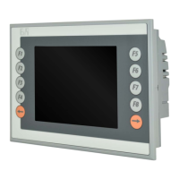
Displays an image of the Power Panel PP21 for identification.
Details the technical specifications and standards compliance for the PP21.
Shows diagrams of the internal structure of the PP21.
Provides dimensional drawings and measurements for the PP21.
Lists model numbers and short descriptions for the Power Panel PP41 and accessories.
Displays an image of the Power Panel PP41 for identification.
Details the technical specifications and standards compliance for the PP41.
Shows diagrams of the internal structure of the PP41.
Provides dimensional drawings and measurements for the PP41.
Explains the function and compatibility of the EX101 expansion module.
Lists the model number and description for the EX101 module.
Displays an image of the EX101 module.
Details the technical specifications for the EX101 module.
Shows diagrams of the EX101 module.
Provides dimensional drawings and measurements for the EX101 module.
Illustrates the installation process for the EX101 module.
Describes the IF370 module for connecting the Power Panel to a CAN network.
Lists the model number and description for the IF370 module.
Displays an image of the IF370 module.
Details the technical specifications for the IF370 module.
Explains the meaning and color of the status LEDs on the IF370 module.
Shows the pin assignment for the CAN interface connector of the IF370.
Provides guidance on mounting the Power Panel, including air circulation and angles.
Indicates that pin assignments are shown on the device label.
Describes how to program the PLC CPU using Automation Studio™™ or PG2000.
Mentions that visualization applications are created using B&R Automation Studio™™.
Explains the meaning and color of the status LEDs on the Power Panel.
Details the 24 VDC power supply and its pin assignment.
Identifies the two interfaces available on the Power Panel: CAN and RS232.
Explains the function of the hex switches for operating mode selection.
Outlines the procedure for downloading or updating the operating system.
Describes the PCMCIA interface, supported cards, and limitations.
Details the slots for screw-in modules and provides an overview of available modules.
Explains data buffering, battery data, and buffer duration.
Covers terminal block connections, circuit diagrams, and connection examples for digital inputs.
Covers terminal block connections, circuit diagrams, and connection examples for digital outputs.
Lists battery specifications like voltage, model number, and storage time.
Provides buffer current details for the panel CPU.
Details the resistance of the décor foil to various chemicals.
Provides a mapping of decimal and hexadecimal codes to characters.
| Brand | B&R |
|---|---|
| Model | PP21 |
| Category | Control Panel |
| Language | English |