Power Panel User's Manual 35
Chapter 1
Power Panel
Power Panel • Description of Components
12.3 Interfaces
The Power Panel has two interfaces:
12.3.1 CAN Interface
The electrically isolated standard fieldbus interface is used for the following tasks:
• Communication with other control systems
• Decentralization and remote I/O expansion using B&R 2003 components and a CAN bus
controller
We recommend using the AC911 T-connector for coupling to a CAN network. A terminal
resistance is integrated into the T-connector for the bus termination, which can be switched on
or off. For more information on wiring CAN fieldbus systems, see chapter 2, "Installation", section
"CAN Fieldbus" in the B&R SYSTEM 2003 User's Manual.
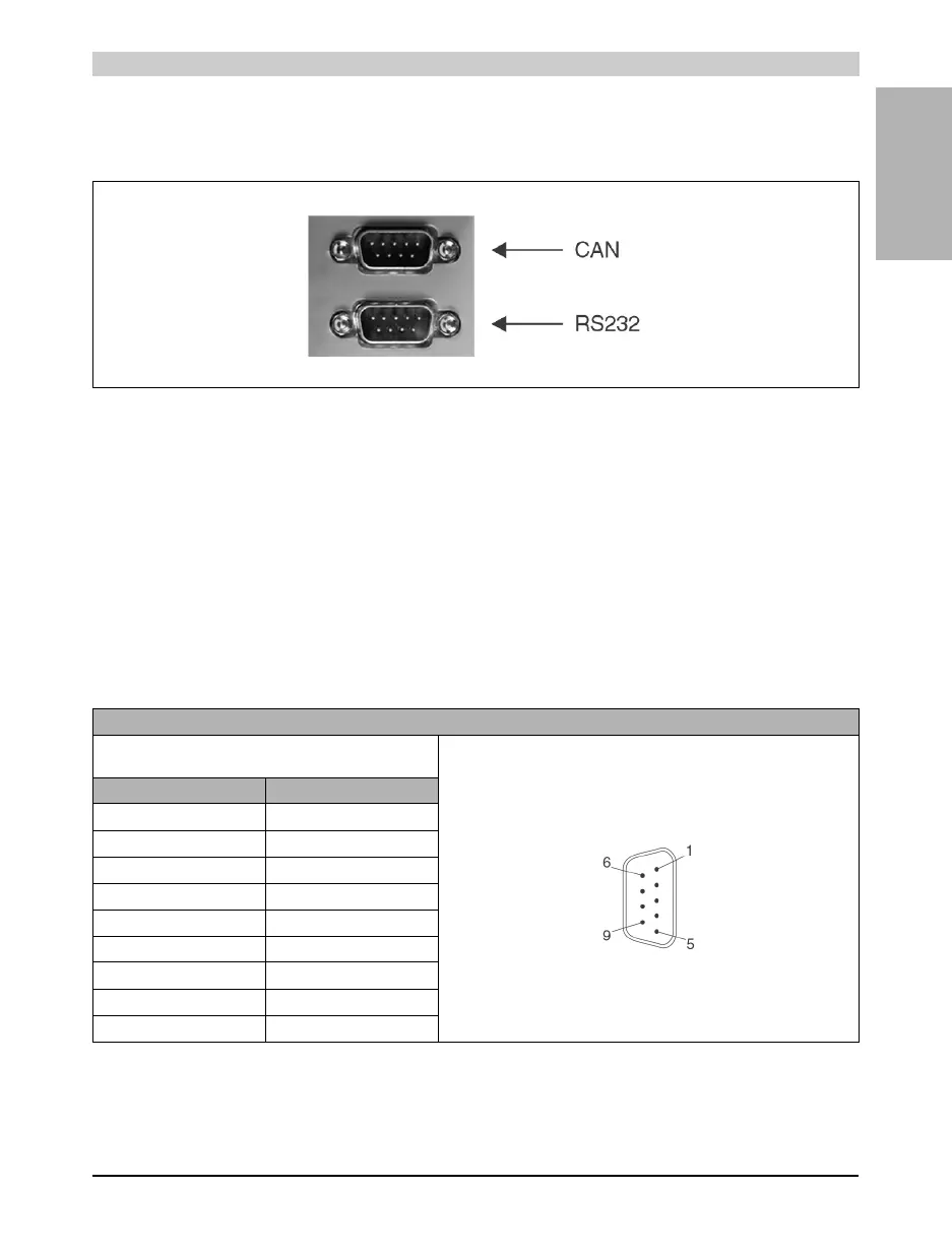
Figure 16: Interfaces
Pin Assignment for CAN Interface
Electrically isolated
Assignment According to CiA DS 102-1
9 pin DSUB plug
Pin Assignment
1n. c.
2CAN_L
3CAN_GND
4n. c.
5n. c.
6Reserved
7CAN_H
8n. c.
9n. c.
Table 17: Pin assignment for CAN interface