36 Power Panel User's Manual
Power Panel • Description of Components
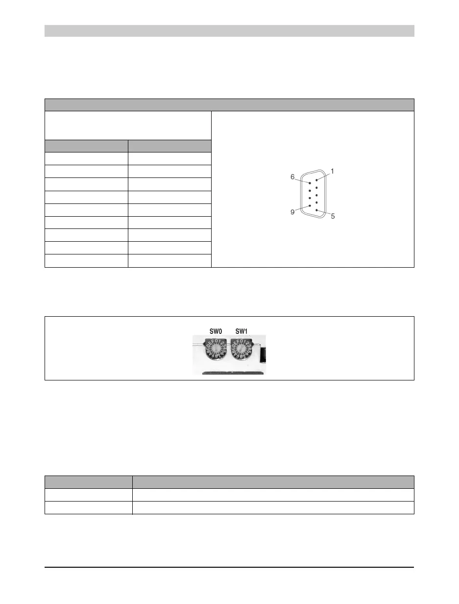
12.3.2 RS232 Interface
This non-electrically isolated interface is primarily intended for programming the CPU. The
RS232 can also be used as a general interface (e.g. printer, bar code reader, etc.).
12.4 Operating Mode Switch
The Power Panels are equipped with 2 hex switches, which are used as an operating mode
switch. Switch positions 01 - FC are available for any purpose in an application. The switch's
position can be evaluated from an application program. The operating system only interprets the
switch position when switched on.
All other switch positions are reserved for special functions.
Pin Assignment for RS232 Interface
RS232 Interface
Not electrically
isolated up to 115 kBaud
9 pin DSUB connector
Pin Assignment
1CTS
2RXD
3TXD
4 +5 VDC /max. 500 mA
5GND
6n. c.
7RTS
8CTS
9GND
Table 18: Pin assignment RS232 interface
Figure 17: Operating mode switch
Switch Position Description
00 Programming System Flash (see respective section)
01 - FC Freely available for use in an application (e.g. CAN node number)
Table 19: Switch settings for the MODE switch