34 Power Panel User's Manual
Power Panel • Description of Components
12. Description of Components
12.1 Status LEDs
12.2 Power Supply
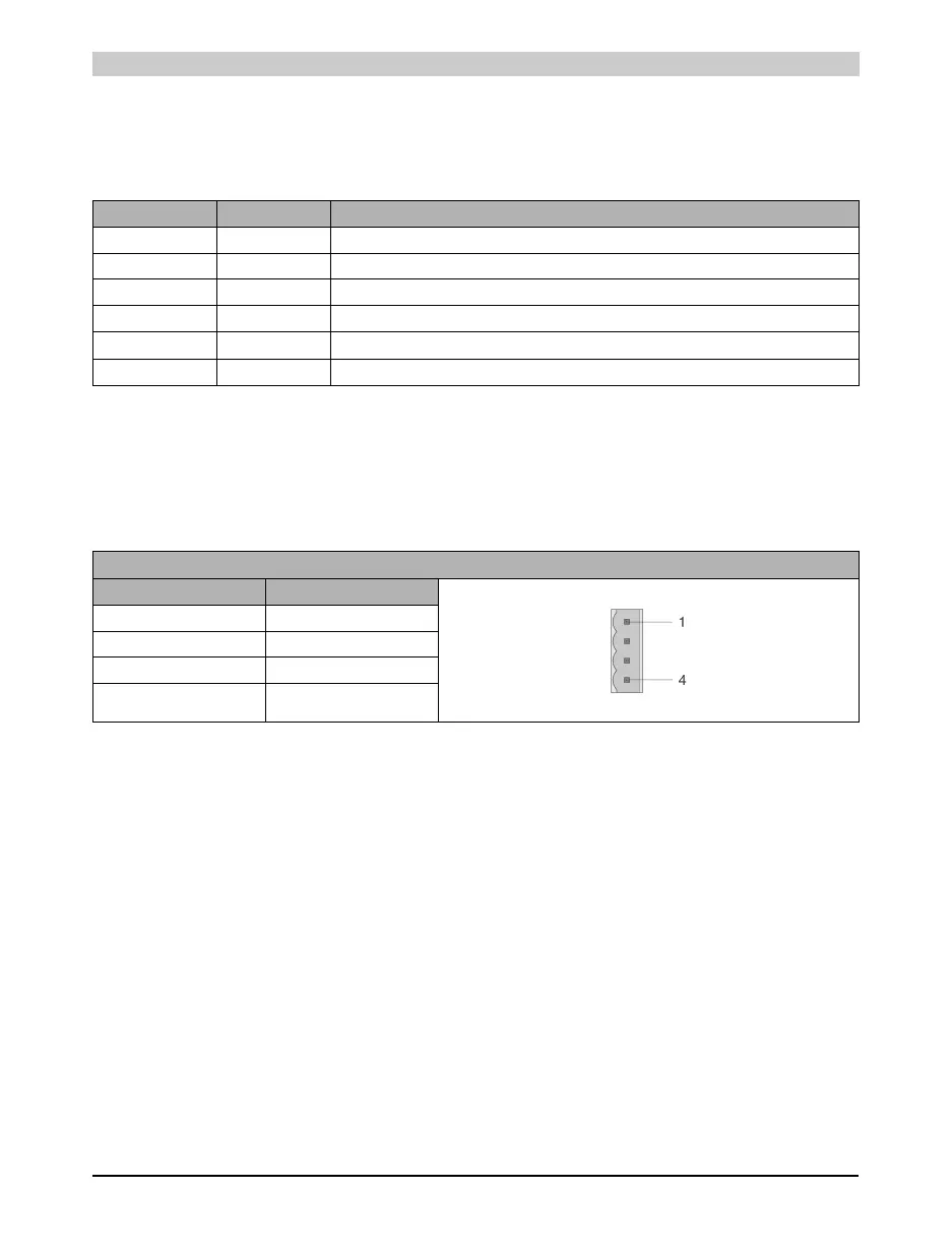
The Power Panel is equipped with a 24 VDC power supply. The pin assignment is printed on the
housing.
Both "+" and "-" pins are connected to each other internally
LED Color Meaning
CAN Yellow Data transfer to or from CAN controller
RS232 Yellow Indicates if data is being transmitted or received
ERR Red Lit in Service mode
RUN Green Lit in RUN and in Service mode
MODE Yellow Lit when programming FlashPROM
READY Yellow Lit in Service mode
Table 15: Status LEDs
Power Supply for Pin Assignment
Pin Description
1+
2+
3-
4-
Table 16: Power supply for pin assignment