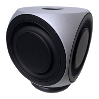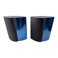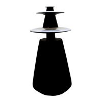
Do you have a question about the Bang & Olufsen BeoLab 5 6881 and is the answer not in the manual?
| Frequency Response | 28 Hz - 23 kHz |
|---|---|
| Type | Active Speaker |
| Connections | RCA |
| Inputs | RCA |
| Color | Black |
| Amplifiers | 5 amplifiers per speaker unit |
Describes front-line service procedures, including part ordering for BeoLab 5.
Refers to the "Service Center repair guide" for part numbers and user guides.
Explains how to change the mains voltage supply and relevant jumper/fuse settings.
Lists BeoLab 5 types with corresponding transformer, jumper, mains cable, and fuse.
Warns about static electricity damaging electronics; advises ESD-mat use.
Advises on careful handling, wearing gloves, and protecting sensitive surfaces.
Introduces PIN code protection and mentions the service master code (11111).
Provides a high-level block diagram of the BeoLab 5's internal circuitry and signal flow.
Details the electrical wiring connections and component layout of the BeoLab 5.
Illustrates and lists parts related to the BeoLab 5 lens assembly.
Lists part numbers for lens components and a survey of screws used in the BeoLab 5.
Illustrates the main speaker driver components and their assembly.
Lists part numbers for speaker components and a survey of screws.
Details part numbers for wire bundles and other accessories like special tools.
Illustrates and lists parts for packing and shipping the BeoLab 5.
Describes no power symptom, causes (protection mode), and solutions.
Details how to check resistance of tweeter, midrange, and woofer units.
Specifies NTC resistor values and how to reset after thermal overload.
Describes the Bang & Olufsen service tool for diagnosis and data management.
Outlines replacing driver units, including EEPROM data transfer.
Details EEPROM replacement, data transfer, and ABC calibration.
Describes replacing the electronic chassis, including moving the EEPROM.
Provides instructions for cleaning the loudspeaker surfaces safely and effectively.
Step-by-step visual guide for replacing the cloth frame on BeoLab 5.
Illustrates the steps to place the BeoLab 5 into a service-ready position.
Detailed instructions for removing and replacing the main electronic chassis.
Guides on how to correctly mount the new main chassis after replacement.
Continues main chassis mounting, including specific fuse changes for US/JPN models.
Step-by-step guide for replacing the 165mm woofer unit.
Detailed instructions for removing and replacing the 381mm woofer unit.
Visual guide on how to replace the foot of the BeoLab 5 speaker.
Step-by-step procedure for replacing the main transformer unit.
Illustrates the process for replacing the microphone unit in the BeoLab 5.
Instructions for replacing the main loudspeaker cabinet, referencing other procedures.
Visual guide for removing and replacing the top plate of the BeoLab 5.
Step-by-step guide for dismantling the lens assembly for the tweeter.
Detailed instructions for replacing the 19mm tweeter unit.
Guides on how to correctly remount the tweeter after replacement.
Instructions for replacing the aluminium plate associated with the tweeter.
Step-by-step guide for replacing the 76mm midrange unit.
Guides on how to correctly remount the midrange after replacement.
Instructions for replacing the aluminium plate associated with the midrange.
Procedure for replacing the top cover of the BeoLab 5.
Details the insulation testing procedure for BeoLab 5 at a service center.
Describes the insulation testing method for when the unit is with the customer.
Warns against skin contact with electrical parts during the insulation test.

