MASTER LINK
TECHNICAL DESCRIPTION
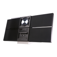
The following section contains a brief description of the cabling most
often used in connection with a BeoLink installation.
Pictures (satellite, video tape recorder and ordinary TV broadcasts) are
distributed through a 75 ohm coaxial cable.
Regarding part nos., see 'Accessories', page 39.
29
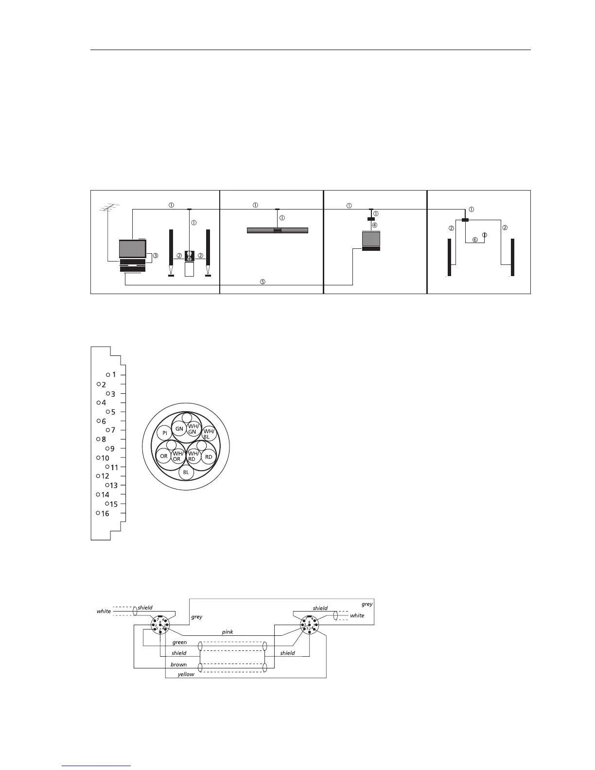
Master Link cable
pin 1 = grey = power up/down
pin 2 = shield = ground
pin 3 = brown= signal, left channel
pin 4 = yellow= loudspeaker relay
pin 5 = green = signal, right channel
pin 6 = white = Datalink
pin 7 = shield = ground
pin 8 = pink = overload
Power Link cable with wire for display data.
Pin no. in the Master Cable colour Function
Link socket
1 white/green (WH/GN) data -
2 green (GN) data +
3 white/blue (WH/BL) ML-sense
4-10 N.C.
11 blue (BL) - supply voltage
12 pink (PI) + supply voltage
13 white/orange (WH/OR) - L
14 orange (OR) + L
15 white/red (WH/RD) - R
16 red (RD) + R
Screen 3 x solid wire Ground
 Loading...