External Device Monitoring
To satisfy the requirements of Control Reliability (OSHA and ANSI), Category 3 and 4 of ISO 13849-1 (EN 954-1), the
master stop control elements (MSCs) must each offer a normally closed, forced-guided (mechanically linked) monitor
contact. Connect one normally closed monitor contact from each master stop control element as shown in the single-
channel wiring diagrams.
In operation, if one of the switching contacts of either MSC fails in the energized condition, the associated monitor contact
will remain open. Therefore, it will not be possible to reset the Safety Module. If no MSC-monitor contacts are monitored, a
jumper must be installed as shown in the wiring diagrams. It is the user's responsibility to ensure that any single failure
will not result in a hazardous condition and will prevent a successive machine cycle.
Overvoltage Category II and III Installations (EN 50178 and IEC 60664-1)
The Safety Module is rated for Overvoltage Category III when voltages of 1 V to 150 V ac/dc are applied to the output
relay contacts. It is rated for Overvoltage Category II when voltages of 151 V to 250 V ac/dc are applied to the output
relay contacts and no additional precautions are taken to attenuate possible overvoltage situations in the supply voltage.
The Module can be used in an Overvoltage Category III environment (with voltages of 151 V to 250 V ac/dc) if care is
taken either to reduce the level of electrical disturbances seen by the Module to Overvoltage Category II levels by
installing surge suppressor devices (for example, arc suppressors), or to install extra external insulation in order to isolate
both the Safety Module and the user from the higher voltage levels of a Category III environment.
For Overvoltage Category III installations with applied voltages from 151 V to 250 V ac/dc applied to the
output contact(s): the Safety Module may be used under the conditions of a higher overvoltage category where
appropriate overvoltage reduction is provided. Appropriate methods include:
• An overvoltage protective device
• A transformer with isolated windings
• A distribution system with multiple branch circuits (capable of diverting energy of surges)
• A capacitance capable of absorbing energy of surges
• A resistance or similar damping device capable of dissipating the energy of surges
When switching inductive ac loads, it is good practice to protect the Safety Module outputs by installing appropriately-sized
arc suppressors. However, if arc suppressors are used, they must be installed across the load being switched (for example,
across the coils of external safety relays), and never across the Safety Module’s output contacts (see WARNING, Arc
Suppressors).
Auxiliary Monitor Contact (Model ES-FA-11AA Only)
The action of the auxiliary monitor contact, terminals 31-32, inversely "follows" the action of the safety outputs. The 31-32
auxiliary monitor contact is to be used only for control functions that are NOT safety-related. A typical use is to
communicate the status of the Safety Module output to a programmable logic controller (PLC).
WARNING: Interfacing MSCs
Do not wire an intermediate device(s) (for example, PLC, PES, PC) between the Safety Module outputs
and the Master Stop Control Element it switches in such a manner that in the event of a failure there is
a loss of the safety stop command, or in such a manner that the safety function can be suspended,
overridden, or defeated, unless accomplished with the same or greater degree of safety.
Whenever forced-guided, mechanically linked relays are added as intermediate switching devices, a
normally closed (N.C.) forced-guided monitor contact from each relay must be added to the series
feedback loop between Safety Module terminals S31 and S32.
WARNING: Wiring of Arc Suppressors
If arc suppressors are used, they MUST be installed as shown across the actuator coil of the stop
control elements (MSCs or MPCEs). NEVER install suppressors directly across the output
contacts of the Safety Device or Module. It is possible for suppressors to fail as a short circuit. If
installed directly across the output contacts, a short-circuited suppressor creates an unsafe
condition which may result in serious injury or death.
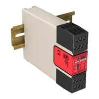
ES-FA-9AA and ES-FA-11AA E-Stop Safety Module
8 www.bannerengineering.com - Tel: +1-763-544-3164 P/N 60606 Rev. G
 Loading...