2
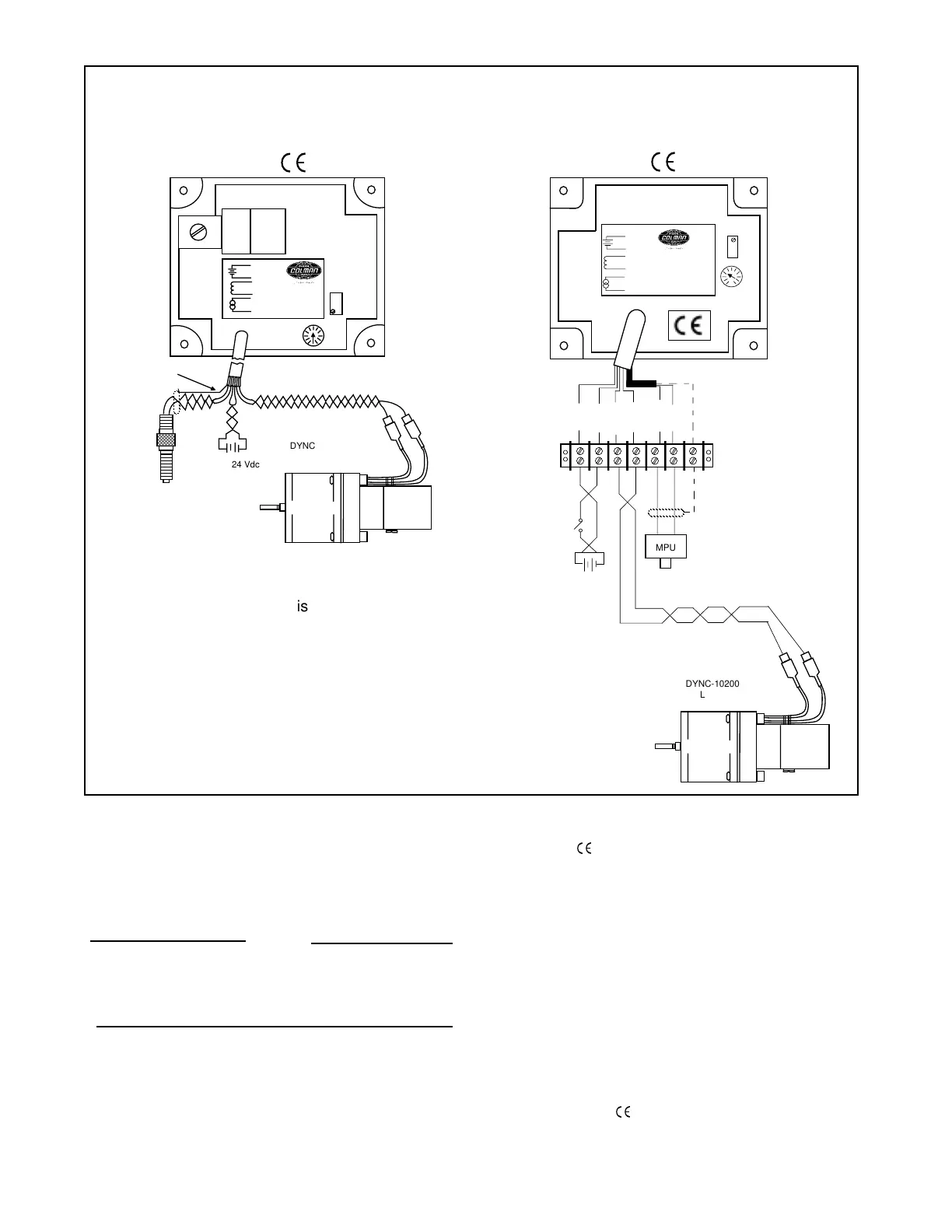
TYPICAL WIRING DIAGRAM
Controllers with conformity are wired as shown in
Figure 2 Wiring Diagram.
Black
Purple
Purple
White
Black
ACT
SPEED
GAIN
+
-
MPU
-
~
Red
0
100
Battery
12 or 24
Vdc Supply
Purple
Black
White
Purple
Black
Red
-
+
MPU
DYNC-10200
Linear
Actuator
Non
General information, wiring and calibration procedure for the DYN1-10704, 10714, 10724 and
10734 controllers for the linear governor system.
CALIBRATION
1. With no power to the governor, adjust the GAIN to
9:00 o’clock.
2. Start the engine and adjust the speed by turning
the SPEED pot clockwise to desired speed.
NOTE
Controllers are factory adjusted to mini-
mum RPM. However, for safety, one should
be capable of disabling the engine if an
overspeed should exist.
3. At no load, turn the GAIN potentiometer clockwise
until the engine begins to hunt. If the engine does
not hunt, physically upset the governor linkage.
4. Turn the GAIN potentiometer counterclockwise
until stable.
WIRING
All four non controllers are wired as shown in
Figure 1 Wiring Diagram.
1. Red to battery positive.
2. Black to battery negative.
3. Purple to the actuator, no polarity.
4. White to one side of the magnetic pickup.
5. Black and white to the other side of the magnetic
pickup connected with the shield drain wire.
Figure 1 Figure 2
Red
Black
Purple
Purple
White
Blk/Wht
MPU
ACT
SPEED
GAIN
+
-
-
~
+
-
MPU
12 or 24 Vdc
Supply
DYNC-10200
Linear
Actuator
Optional
Connections
Customer has option
on how to connect
leads to controller.
*See color
code on front
of controller.
*
Note: The shield on the MPU is to be connected to
the black wire along with one of the MPU
conductors.

 Loading...