Manual 2100-705B
Page 27 of 43
Wall-Mount Unit 1
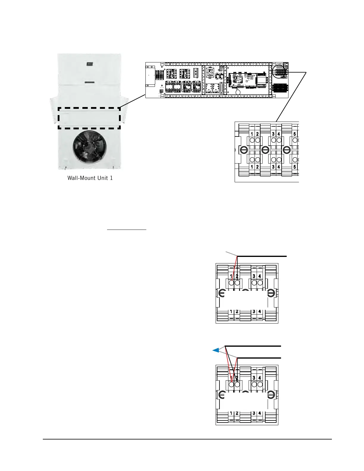
FIGURE 24
Communication Wiring: Termination at the First Wall-Mount Unit
1. From the controller, extend the shielded cable through a separate
conduit and route to terminal #1 (positive) and terminal #2
(negative) on the upper terminal block next to the wall-mount
control board on the unit control panel.
These connections are polarity-sensitive. Two-wire communication
from control board is prewired to terminal block. Make sure to
match "+" and "-" symbols on the Field Wiring label above the
terminal block.
2. Connect the wires matching the terminal
designations (+/-) of the Field Wiring
label. Leave the drain wire loose.
3. Connect another cable in a similar
fashion (“daisy chain”) to route in
conduit to the second wall-mount unit.
Connect both drain wires with wire nut.
Maximum two wires per terminal.
To Wall-Mount Unit 2
––
++
From LC6000
Controller
Unit 1
Terminal Block
––
++
From LC6000
Controller
Unit 1
Terminal Block