Manual 2100-692H
Page 6 of 44
Duct Work
All duct work, supply and return, must be properly
sized for the design airow requirement of the
equipment. Air Conditioning Contractors of America
(ACCA) is an excellent guide to proper sizing. All duct
work or portions thereof not in the conditioned space
should be properly insulated in order to both conserve
energy and prevent condensation or moisture damage.
Refer to Maximum ESP of Operation Electric Heat table
on page 40.
Design the duct work according to methods given by
the Air Conditioning Contractors of America (ACCA).
When duct runs through unheated spaces, it should
be insulated with a minimum of 1" of insulation. Use
insulation with a vapor barrier on the outside of the
insulation. Flexible joints should be used to connect the
duct work to the equipment in order to keep the noise
transmission to a minimum.
All model series require a 1/4" clearance to
combustible material for the rst 3' of duct attached
to the outlet air frame is required. See instructions
on page 11 and Figures 14 − 18 (pages 14 – 17) for
further details.
Ducts through the walls must be insulated and all joints
taped or sealed to prevent air or moisture entering the
wall cavity.
Some installations may not require a return air duct. A
metallic return air grille is required with installations
not requiring a return air duct. The spacing between
louvers on the grille shall not be larger than 5/8".
Any grille that meets with 5/8" louver criteria may be
used. It is recommended that Bard Return Air Grille
Kits RG5 or RFG5 be installed when no return duct
is used. Contact distributor or factory for ordering
information. If using a return air lter grille, lters must
be of sufcient size to allow a maximum velocity of
400 fpm.
NOTE:
If no return air duct is used, applicable
installation codes may limit this cabinet to
installation only in a single story structure.
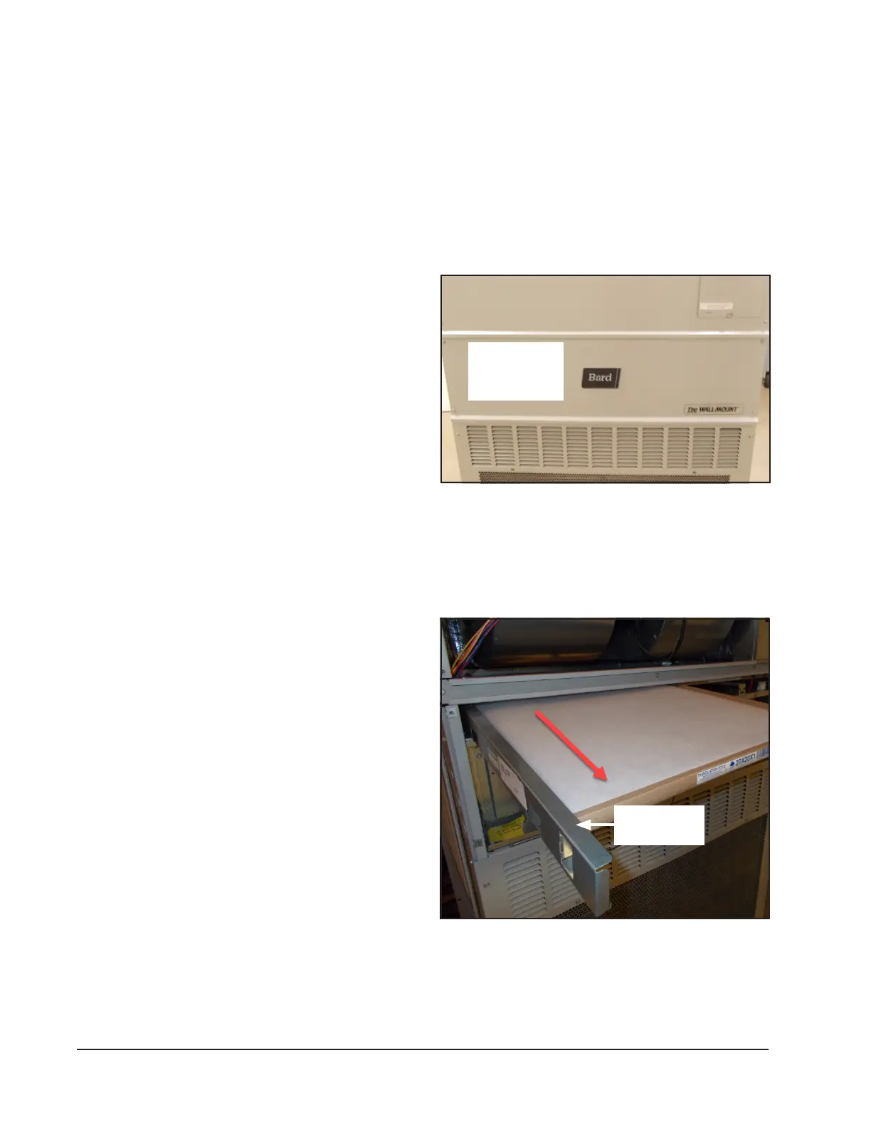
Filters
The lters can be serviced from the outside by
removing the front control panel cover (see Figure 1).
Two (2) 20" x 20" x 1" throwaway lters come standard
with each unit. Additional 1" and 2" lter options are
available as optional accessories. To be notied when
lters need changed, a dirty lter switch option is
available. See page 40 for the dirty lter switch kit.
2. Slide second lter to the left around the wires and
pull the lter out (see Figure 3).
FIGURE 1
Front Control Panel Cover
Front
Control Panel
Cover
Filter Removal/Installation
1. Remove left lter rst by pulling on lter removal
slide (see Figure 2).
FIGURE 2
Removing Left Filter
Filter Removal
Slide