Manual 2100-692H
Page 7 of 44
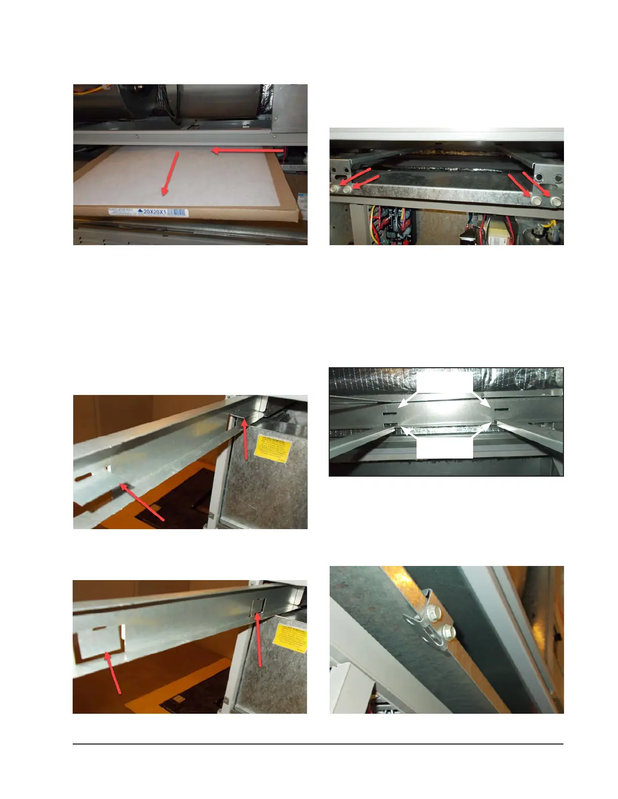
2. Locate the lter support brackets and remove the
four (4) screws holding them to the top of the
control panel (see Figure 6).
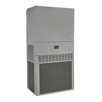
FIGURE 4
Filter Tabs in Up Position
FIGURE 5
Bend Filter Tabs Down
3. Pull the brackets out towards the front of the unit.
The back of the bracket will slip out of the upper
slots at the back of the lter tray.
4. Re-install the lter support brackets into the lower
slots at the back of the lter tray (see Figure 7).
FIGURE 6
Remove Four Screws
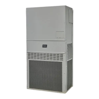
5. Re-install the four (4) screws into the upper screw
holes on the lter support brackets. Then bend the
tab up out of the way (see Figure 8).
FIGURE 7
Re-Install Filter Support Brackets into Lower Slots
FIGURE 8
Re-Install Screws and Bend Tabs Up
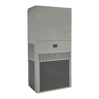
FIGURE 3
Removing Second Filter
3. Reverse the order for new lter installation.
NOTE: When installing new filters, make sure that
airflow arrows on filters point up.
Switching Filter Sizes
1. To switch from 1" to 2" lters, start by removing
the lter slide and bend the tabs down out of the
way (see Figures 4 and 5).
Upper slots for
1" lters
Lower slots for
2" lters