Version 1.25 | E3 IP66 Outdoor Rated User Guide | 7www.bardac.com
Mechanical Installation
3
3. Mechanical Installation
3.1. General
The E3 drive should be mounted in a vertical position only, on a flat, flame resistant, vibration free mounting using the integral
mounting holes.
Do not mount flammable material close to the E3 drive.
Ensure that the minimum cooling air gaps, as detailed in section 3.4. Guidelines for mounting on page 8.
Ensure that the ambient temperature range does not exceed the permissible limits for the E3 drive given in section 10.1.
Environmental on page 54.
3.2. UL Compliant Installation
Refer to section 10.5. Additional Information for UL Compliance on page 55 for Additional Information for UL Compliance.
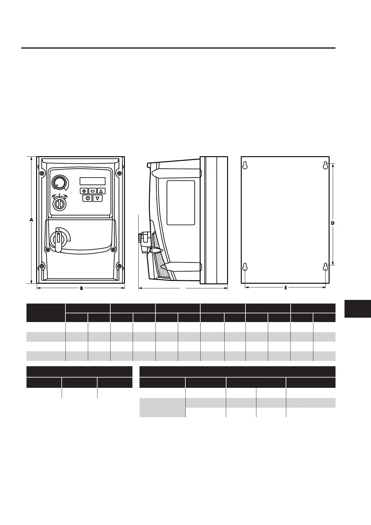
3.3. Mechanical Dimensions
Drive Size
A B C D E
Weight
mm in mm in mm in mm in mm in kg Ib
1 232 9.13 161 6.34 162 6.37 189 7.44 148.5 5.85 2.3 5
2 257 10 .12 18 8 7. 4 182 7.16 200 7. 87 178 7.00 3.5 7. 7
3 310 12.2 211 8.3 235 9.25 252 9.92 197 7. 75 6.6 14.5
4 360 14 .17 240 9.44 2 71 10.67 300 11 . 81 227 8.94 9.5 20.9
Mounting Bolts Tightening Torques
Frame Size Metric UNF Frame Size Required Torque Terminal Type
All Sizes M4 #8 Control Terminals All 0.5 Nm 4.5lb-in Rising Clamp
Power Terminals
1 - 3 0.8 Nm 7 lb-in Rising Clamp
4 2 Nm 18 lb-in Rising Clamp