61-101-00802.EF1 Revision J Page | 24
Aircraft 200, 250, 300, 350 / 350i & 360
100-380006-11, -69, -105, -139, -143, -175
100-380006-55, -81, -115, -177
100-380006-37, -71, -107, -141, -145, -173
100-380006-93, -121, -179
100-380006-95, -123, -181
100-380006-41, -77, -113, -171
100-380006-35, -85, -119, -169, -197
100-380006-33, -57, -83, -117, -149, -151,
-167
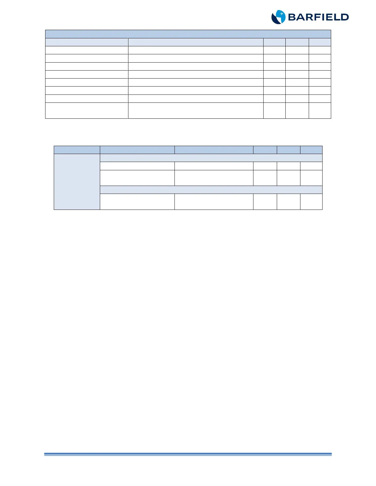
Table 11 Probe Capacitance Full (pF)
A100, B100,
200, 250,
300 / 350i,
360, E90
Aircraft with 100-380006-59 Harness
Cable Assy & Integral
Tank Units
Aircraft with 100-380006-99, -127 Harness
Cable Assy & Integral
Tank Units Combined
100-380006-93, -95,
-121, -123, -179, -181
Table 12 Probe Capacitance Full (pF)
Note: The probes and harnesses in Table 12 were installed in aircraft with S/N LW17,
LW69 through LW214, B152, B156 through B234, BE1 through BE24 and BB2
through BB220.
Note: The -59 harness has diodes mounted in it and can be tested without any probes
attached.
The -15 and -17 probe cannot be tested without the –59 harness attached.
Note: Refer to Beech Service Bulletin, 0648-355, for replacement P/N’s of the 100-
380006-15, 17, & 59 cables and probes.
(5) Set the T/S ON / OFF switch to OFF.
(6) Rotate the TEST FUNCTION switch to IND AMP.
(7) Set the INSULATION / SYSTEM switch to INSULATION.
(8) Disconnect the pin socket ground lead of the probe adapter (small black lead) from
the ground clip pigtail.
(9) Rotate the INS TEST POINT switch to LO-Z GND.
(10) Set the ON / OFF switch to ON.
(11) Allow time for T/S display to stabilize.
Note: On those occasions when display stabilization cannot be achieved, take the
reading after performing this test for 30 seconds. If this value is in the
acceptable range, then consider that the probe has passed this test.
(12) Verify the T/S display shows less than 50 nS (refer to Table 1).
(13) Rotate the INS TEST POINT switch to each remaining position except SIG / RTN
and verify each time that the T/S display shows less than 50 nS.