17
17
MODEL SR124
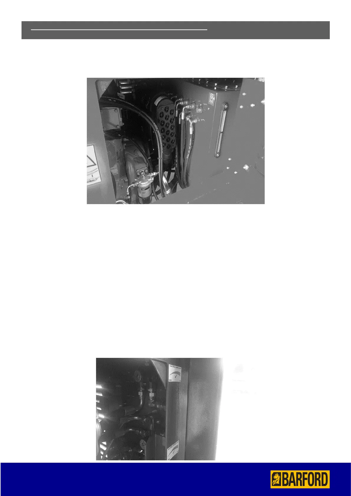
HYDRAULIC TANK INDICATOR AND RETURN LINE FILTER
The indicator is located at the side of the hydraulic tank, the return line filter is located on the top of the hydraulic tank.
SHUT DOWN OF DIESEL/ELECTRIC POWERED CONVEYOR
• Observe all safety warnings. Make sure the conveyor is empty and clear of all materials.
• Empty the conveyor.
• Lower the engine revs by lowering the hand throttle.
• Stop the main conveyor unit.
• Stop the engine.
OVERSIZE AND FEEDER CONVEYORS FLOW CONTROL VALVES.
• In Addition to the control valves your machine is fitted as standard with a variable speed control for the Feeder/Oversize
conveyor. It is located inside the power unit.
• This is clearly labeled and should be used to adjust the feed rate of material onto the Screen box. The Belt feeder feed rate
will be different in each application depending on the raw material to be screened to maximize throughput and screening
efficiency.
6) POWER UNIT AND CONTROL VALVES CONTINUED