Technical data subject to change without notice 01-3400-7D0001/REV-A-12-2022/ESS-4619265 / 8
BARTEC Operational Instructions – Control and signal device actuators and accessories
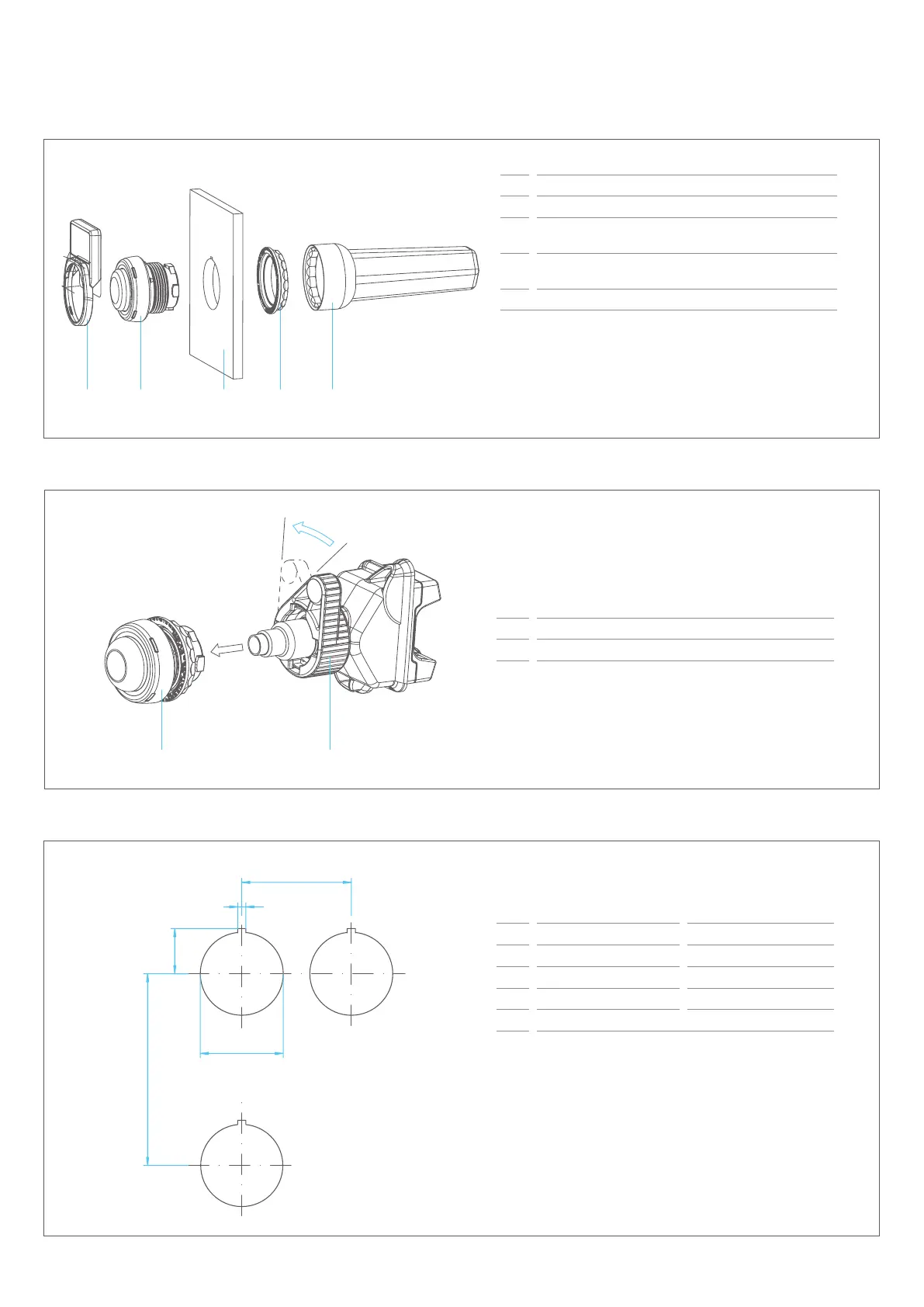
Mounting of the actuators
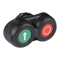
Assembly of Functional Modules with Bayonet Fixing
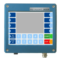
Installation Dimensions
1 shield holder
2 Control and signal device actuator
3 Enclosure with wall thickness of 1 to 6 mm (0.04 to
0.24 in) with a mounting hole 30.3
+0.3
mm (1.2+0.01 in)
4 Fixing nut, must be tight a torque of 2.8 - 3.4 Nm
(2 - 2.5 lb.ft)
5 Torquing tool
The control and signal device actuators may optionally be
provided with one of the following accessories:
- protective collar
- locking device
- shield holder
- marking clip
- printed labels
1 Control and signal device actuator
2 ComEx module type 07-33**-****/****
mm in
A 75 2.95
B 16.5
+0.2
0.65
+0.008
C Ø 30.3
+0.3
Ø 1.2
+0.01
D 3
+0.1
0.12
+0.004
E 40 1.6
Mounting hole with cut-out for anti-twist protection, typical
position: top (12 o’clock position).
Minimum spacing for the mounting boreholes:
– horizontal 40 mm (1.6 in)
– vertical 70 mm (2.8 in)
Chamfer or rounding from 0.1 mm up to 0.3 mm
(0.004 up to 0.01 in) on outer surface of hole is required.
D
B
C