EasyManua.ls Logo

Bartell B436 User Manual

Bartell B436
46 pages
To Next Page IconTo Next Page
Page #1 background imageLoading...
Page #1 background image
WALK-BEHIND
POWER TROWELS
B430
B436
B436E
B436SD
B440
B446
Doc. # OI-B09001
Orig. Rel. - 05-2010
Curr. Rev. - 00
Rev. Date - 05-2010
Bartell Morrison Inc.
375 Annagem Blvd.,
Mississauga, ON, Canada
L5T 2A7
Toll Free (N.A.): 1 866 501 1683
Local: +1 905 364 4200
Fax: +1 905 364 4201
OWNER’S
MANUAL
BARTELL MORRISON INC.
artell
ORIGINAL
LANGUAGE
B436
B436E
B436SD
B446
B446 Mega T
Doc. # OI-B09001
Orig. Rel. - 05-2010
Curr. Rev. - 04
Rev. Date - 08-2014

Other manuals for Bartell B436

Question and Answer IconNeed help?

Do you have a question about the Bartell B436 and is the answer not in the manual?

Bartell B436 Specifications

General IconGeneral
BrandBartell
ModelB436
CategoryTrowels
LanguageEnglish

Summary

Safety Precautions

Quality Assurance / Machine Break In

Walk-Behind Power Trowel Warranty

Maintenance Record

Routine Service Intervals

Assembly Instructions

Trowels

Attaching trowel blades with screws and lock washers.

Stabilizer Ring

Installing the stabilizer ring if supplied.

Handle

Instructions for installing the handle, referring to Setup Procedure.

Setup Procedure

Step 1: Trowel shown with handle separate

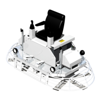
Illustration of trowel with handle separated for assembly.

Step 2: Lay handle on ring to prepare for assembly

Preparation of the handle for assembly onto the ring.

Step 3: Install pitch control cable to yoke

Installation of the pitch control cable to the yoke.

Step 5: Unwrap throttle control and safety wires

Unwrapping throttle and safety shut-off wires for assembly.

Step 6: Remove air filter cover and filter

Removal of the air filter cover and air filter.

Step 7: Check free moving throttle control lever

Verification of free movement of the throttle control lever.

Step 8: Push handle throttle lever to idle

Setting the handle throttle lever to the idle position.

Step 9: Install throttle control wire

Connection of the throttle control wire to the lever.

Step 10: Secure wire to cable clamp

Securing the throttle wire to the cable clamp.

Step 11: Check throttle control lever operation

Verification of throttle control lever operation.

Step 12: Reinstall air filter and cover

Reinstallation of the air filter and its cover.

Step 13: Route and install engine safety shut-off wire

Routing and installation of the engine safety shut-off wire.

Step 14: Wrap and secure engine safety shut-off wire

Wrapping and securing the engine safety shut-off wire.

Step 15: Refer to Owner's Manual

Final instruction to consult the Owner's Manual before operation.

Operation (Floating)

Operation (Finishing)

Stopping Procedure

Lubrication

Engine Oil

Instructions for checking and maintaining engine oil levels.

Spider Plate

Daily greasing requirement for spider plate fittings.

Gearbox

Checking gearbox oil levels and capacity.

To Change Gearbox Oil

Procedure for draining and refilling gearbox oil.

Storage

Maintenance

Air Cleaner

Instructions for cleaning the air filter.

Lubrication

Regular checking of engine oil.

Spark Plug

Procedure for checking and cleaning spark plugs.

Belt

Guidelines for checking belt condition and replacement.

Electric Power Trowel Operation

Setting Up The Electric Power Trowel

Starting The Electric Power Trowel

Electric Power Trowel Wiring Diagram

Trowel Arm Adjustment Fixture

Adjustment Procedure

Step-by-step guide for adjusting trowel arms using the fixture.

Trowel Arm Adjustment Screw

Guidance on using the adjustment screw for field adjustments.

Troubleshooting

Specifications

Declaration of Conformity

Technical Characteristics

Notes

General Assembly - B446

General Assembly - B446 w/CVT

Base Unit Assembly

Handle Assembly - 20562 Fine Pitch

Handle Assembly - 20611 European Spec.

Gearbox Assembly - 20928

Clutch Assembly - 21029 (1" Shaft)

Spider Plate Assembly - 20820

Pressure Plate Assembly - 20626

Blade Kit Assembly

Related product manuals