9
3-6. Complete Calibration (Cont.) (DP=Differential Pressure)
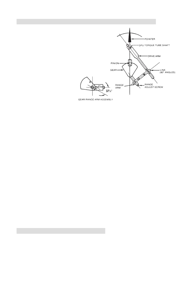
2. Attach linkage between drive arm and
movement. Fig. 3-3 shows alignment
at 50% DP. Inspect parts for straight-
ness and pivot-t without binding.
3. Set pointer at zero on scale by slip-
ping pointer on hub. Hold tip of
pointer and turn hub with wrench.
4. Apply 100% DP. If pointer exceeds
100% on scale,
lengthen range arm.
Remove pressure.
5. Set zero and span,
using hub for zero
adjustment and
range adjust screw
on the movement for span adjustments.
6. Apply 50% DP. If pointer does not indicate 50% scale, a linearity adjust-
ment is necessary. Loosen drive arm screw and move arm to shift pointer
in direction of error (approx. 10:1). Tighten drive arm screw.
7. Release pressure and reset pointer at zero. Check the span. If gear in move-
ment reaches limit of travel as a result of linearity adjustment (step 6), slip
range arm along gear approximately 5 degrees from normal 37.5 degree
angle to approximately 43 degrees. Range arm is slipped by applying pres-
sure to range arm with thumb, while holding gear rmly in place. Retest
pointer response at 50% and 100% DP, and adjust linkage until readings
are acceptable.
8. Apply 0%, 25%, 50%, 75%, 100%, 75%, 50%, 25%, and 0% of DP
consecutively to instrument without overshoot. Lightly tap indicator to over-
come friction. Pointer should accurately indicate each applied pressure.
10. Test instrument repeatability by applying 0%, 50%, 0%, 50% DP. Indicator
should accurately indicate each applied pressure.
11. Set overrange stops to prevent pointer from striking snubbers on scale. See
para. 3-7 (Overrange Stop Adjustment). Tighten all screws. Test setting by
manually moving pointer from zero position to 50%, then let the pointer
return freely. An off-set in zero reading indicates pointer slippage. If neces-
sary, tap pointer hub to tighten it to shaft.
3-7. Overrange Stop Adjustment
1. Apply sufcient pressure to the high pressure housing to deect the pointer
against the snubber on the scale plate. Slide the upper overrange stop
against the drive arm and tighten the overrange stop screw.
2. Apply sufcient pressure to the low pressure housing to deect the pointer
against the zero stop snubber on the scale plate. Slide the zero-stop against
the drive arm and tighten the zero-stop screw.
3. Remove the pointer and calibration scale. Replace the pointer at zero
(adjust zero as necessary). Replace the lens and bezel assembly.
Figure 3-3. Linkage at 50% DP