The Barton Differential Pressure Indicator, available in Models 200A, 227A, and 227C, is an instrument designed to measure differential pressure, fluid flow rate, or liquid level. For fluid flow applications, it connects via piping to the high and low-pressure sides of a primary device, such as orifice plates or venturis, within the process run. In liquid level applications, the indicator translates changes in differential pressure, caused by variations in liquid level within a process vessel, into a liquid height reading.
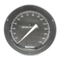
The core of the indicator's function lies in its actuating unit (DPU), which contains bellows that respond to differential pressure changes. This movement is mechanically transferred to the indicator mechanism through a rotating torque tube shaft. As the torque tube rotates, a drive arm transmits the motion via a connecting link to the indicating pointer. This pointer then traverses a 270-degree arc across a six-inch diameter scale plate, providing a visual representation of the measurement. The scale plates can be customized to display readings in uniform increments for differential pressure, static pressure, or liquid height, or in square-root increments for direct flow measurements. Specialized scales can also be provided to indicate the volume of liquid in a tank.
The indicator's movement incorporates a micrometer screw for precise range adjustment. Pointer hub adjustments can be performed without needing to remove the scale plate or the pointer itself. For more extensive range and linearity adjustments, access is gained after removing the scale plate.
Installation of the Barton Differential Pressure Indicator requires careful attention to the instructions provided in the manual, as well as the separate DPU manual specific to the instrument model. It is crucial to inspect the instrument upon unpacking for any shipping damage. For applications demanding special cleaning or precautions, the instrument is protected by a polyethylene bag, which should only be removed in extremely clean environments to prevent contamination. When mounting, piping, or installing the DPU, users must refer to the appropriate DPU manual. A critical warning during installation is to never turn the instrument by grasping its case, as this can cause damage; instead, always thread pipes into the instrument. Startup procedures, including important warning notices, are also detailed in the separate DPU manual for the specific instrument model.
Maintenance and calibration are essential for ensuring the indicator's accuracy and longevity. A set of required tools, including a pointer puller, small and medium screwdrivers, a spanner wrench, and an open-end wrench, are necessary for various adjustments. The bezel and lens assembly, which protects the indicator, must always be installed with the bezel gasket correctly oriented to prevent the indicator from jamming and causing inaccurate readings. To remove the bezel and cover lens, three screws on the front of the bezel are loosened, the bottom is tilted out, and the bezel is slid upward. It's important to ensure that the two snubbers on the scale plate do not compress against the lens cover and that the pointer does not touch the lens.
A calibration check is typically performed to verify the factory-set calibration. This involves mounting the indicator in a level position, connecting the DPU to a standard pressure source, and checking the zero indication. If the zero is incorrect, the bezel/lens is removed, and the pointer is reset to zero by holding it with fingers and turning the hub with a wrench. Reverse travel is tested by connecting the pressure source to the low-pressure housing and venting the high-pressure housing, applying approximately 150% of the differential pressure range; the pointer should move 5% to 10% below zero. Overtravel is checked similarly by applying pressure to the high-pressure housing and venting the low-pressure housing, with the pointer moving 5% to 10% above full scale. The instrument's accuracy is then verified at 0%, 50%, and 100% of full scale pressure. If indications are outside specified limits, a complete calibration procedure is required.
Pointer installation involves positioning the pointer on the movement shaft at the zero scale, potentially enlarging the hub hole with a tapered broach, and lightly tapping the hub with a hand-set. After checking calibration, the pointer is secured by tapping the hub. Pointer removal is done using a Barton Pointer Puller, sliding it along the pointer until its screw pin is over the movement shaft and its arms are under the pointer, then gently turning the knurled head clockwise to lift the pointer.
A complete calibration is necessary when the DPU assembly is replaced, following the procedures in the separate DPU manual. This involves attaching the linkage between the drive arm and movement, setting the pointer at zero, applying 100% DP and adjusting the range arm if needed, and setting zero and span. Linearity is adjusted by loosening the drive arm screw and moving the arm. If the gear reaches its travel limit, the range arm is slipped along the gear. The instrument's response is then retested at 50% and 100% DP. Repeatability is tested by applying 0%, 50%, 0%, 50% DP. Overrange stops are adjusted to prevent the pointer from striking the snubbers on the scale plate.
DPU maintenance, including inspection, cleaning, repair, and service procedures, along with applicable warnings, are detailed in the separate DPU manual. Locking the drive arm to the torque tube involves slipping the drive arm over the torque tube shaft, ensuring a 0.030-inch clearance from the torque-tube housing, and then tightening the clamp screw until snug, followed by an additional 1/3 to 1/2 turn for sintered blocks or 1/4 to 1/3 turn for slotted blocks.
Troubleshooting information is provided to address common issues such as low or no indication, high indication, and erratic indication. For problems originating from the DPU, piping, or primary element, users are directed to the separate DPU manual. Indicator-specific issues like loose movement, being out of calibration, dirty or corroded mechanisms, or a loose pointer can be resolved by tightening/replacing the movement, calibrating the unit, cleaning/replacing the mechanism, or tightening the pointer. If the movement is dragging or dirty, or the pointer is dragging on the scale plate, adjustment or cleaning of the movement and adjustment of the pointer position are recommended.