21
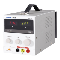
7. Connection Contacts and Control Elements
The figures are located on the next page.
(1) LED display “A” for output current
(2) LED display “V” for output voltage
(3) LED display for active output sockets
(4) Pushbutton for activation/deactivation of the output sockets
(5) Rotary control “VOLTAGE” for general voltage adjustment
(6) Rotary control “FINE” for fine voltage adjustment
(7) Plus connection sockets for direct current output
(8) Connection socket for earth connection (yellow-green)
(9) Minus connection sockets for direct current output
(10) On/off switch
(11) Rotary control “CURRENT” to limit output current
(12) LED display “CV” for voltage control for the output
(13) LED display “CC” for current control for the output
(14) Cooling fins
(15) Fuse holder
(16) Mains input socket