ZENITH SERIES
7
EXPANDABLE/RETRACTABLE SLEEP DECK SUPPLEMENTAL MANUAL
GF Health Products, Inc. - www.grahamfield.com Expandable/Retractable Sleep Deck Supplement 999-0881-190D JANUARY 2014
HEADBOARD AND FOOTBOARD POSITIONS
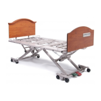
USING THE QUICK-RELEASE “DETENT” PINS
80” hole
position
(1st bottom
hole in)
Use 1st hole
in mounting
tubes for both
76” and 80”
positions
76” hole
position
(2nd bottom
hole in)
BOARD SHOWN AS
TRANSPARENT
FOR CLARITY
80” hole
position
(2nd bottom
hole in)
“Detent” Pin (attached
to frame with Lanyard)
“Detent” Pin (attached
to frame with Lanyard)
Use 1st hole
in mounting
tubes for both
76” and 80”
positions
76” hole
position
(3rd bottom
hole in)
CENTER
OF BED
CENTER
OF BED
IMPORTANT
HEAD & FOOTBOARD
MUST MATCH RETAINER
& WALLSAVER POSITIONS.
SEE EACH BED MODEL’S
SERVICE MANUAL.
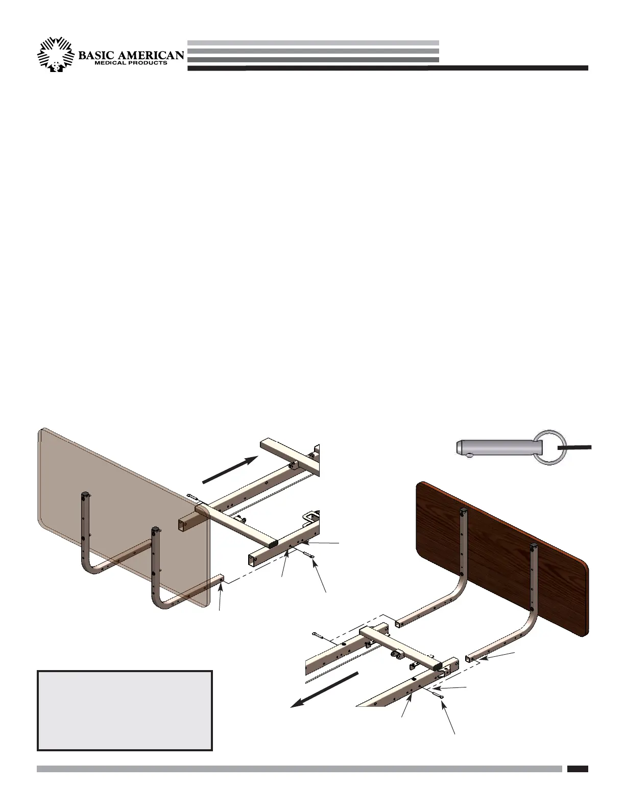
HEADBOARD INSTALLATION
1. The Headboard comes with four pre-installed inserts -
consider this the inside of the bed (toward center).
2. Attach the boards as shown using the 40mm hex drive
bolts that came with your Panel Mounting Kit.
a. Align top holes in board with TOP holes
in the mounting tubes.
b. From the outside of the tubes, insert the
hex drive bolts and screw them into the
board inserts.
c. Insert a second set in the THIRD holes
down on the tubes and screw into board.
3. Slide the “L” portions of the Mounting Tubes into the hollow
ends of the main frame rails at the head deck end. Align
the first hole in the mounting tube with the first or second
hole in the main frame rail (see 76” and 80” positions
below). From the outside, insert the attached “detent”
pin (with Lanyard) through the holes. The recessed ball
on the pins should extend out the other side of the rail.
FOOTBOARD INSTALLATION
1. The Footboard comes with four pre-installed inserts -
consider this the inside of the bed (toward center).
2. Attach the boards as shown using the 40mm hex drive
bolts that came with your Panel Mounting Kit.
a. Align top holes in board with TOP holes
in the mounting tubes.
b. From the outside of the tubes, insert the
hex drive bolts and screw them into the
board inserts.
c. Insert a second set in the FOURTH holes
down on the tubes and screw into board.
3. Slide the “L” portions of the Mounting Tubes into the hollow
ends of the main frame rails at the foot deck end. Align
the first hole in the mounting tube with the first or second
hole in the main frame rail (see 76” and 80” positions
below). From the outside, insert the attached “detent”
pin (with Lanyard) through the holes. The recessed ball
on the pins should extend out the other side of the rail.
FOOTBOARD
HEADBOARD
5/16 X 1.625”
Detent Pin with Lanyard
(Part # 100-7931-011)
Quantity = 4 (two per board)