9252000991 Rev N BE1-50/51B Controls and Indicators 2-3
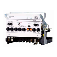
Table 2-1. BE1-50/51B Controls and Indicators (Refer to Figures 2-1 and 2-2)
Locator Control or Indicator Function
A INST MANUAL TRIP
Test Points
When shorted, the test points (jacks) provide a secure means to
manually trip the controlled breaker. Jacks accept a standard 0.08
inch diameter phone tip plug.
B INST PICKUP
Selectors
Two switches (TENS and UNITS on five ampere models,
COARSE and FINE on one ampere models) to select pickup
current in amperes. Changing switch selectors while the relay is in
service may cause tripping.
C Targets
Red target indicators latch when the trip circuit current is greater
than 0.2 amperes. One target each for TIME and INST.
D TIME PICKUP
Selectors
Two switches (TENS and UNITS on five ampere models,
COARSE and FINE on one ampere models) to select pickup
current in amperes. Changing switch selectors while the relay is in
service may cause tripping.
E
CURVE Selector Ten position selector switch to select one of nine inverse functions
or one fixed time function.
F
TIME DIAL Selectors Two selector switches (UNITS and TENTHS) to select the desired
characteristic curve. A setting of 0.0 results in instantaneous
operation without any intentional delay. A setting of 9.9
corresponds to the typical time provided by an electromechanical
relay at its maximum dial setting.
G TIME MANUAL TRIP
Test Points
When shorted, the test points provide a secure means to manually
trip the controlled breaker. Jacks accept a standard 0.08 inch
diameter phone tip plug.
H
ACTIVE/PICKUP LED Red LED indicates sensed current has exceeded the TIME
PICKUP setting. LED turns from red to green when sensed current
falls below 95% of pickup setting. When the LED is green, the
relay is active but has not picked up.
I
Target RESET Button Linkage extends through back of front cover to reset both gravity
latched target indicators.
SW3-1
SW3-1 selects the system operating frequency. Opening SW3-1
(OFF) selects 60 hertz operation. Closing SW3-1 (ON) selects 50
hertz operation.
SW3-2
SW3-2 selects additional delay for the instantaneous element.
Closing SW3-2 (ON) provides an additional instantaneous delay of
0.1 seconds.
SW3-3
100 Series Relays
Closing SW3-3 (ON) provides an additional instantaneous delay of
0.2 seconds. Closing both SW3-2 (ON) and SW3-3 (ON) provides
an additional instantaneous delay of 0.3 seconds.
200 Series Relays
Opening SW3-3 (OFF) selects ABB type curves (refer to Table 1-
3.) Closing SW3-3 (ON) selects GE IAC type curves (refer to
Table 1-4).
J
SW3-4
SW3-4 provides selection of either instantaneous or integrating
reset characteristics. Closing SW3-4 (ON) selects integrating reset
characteristics. Opening SW3-4 (OFF) selects instantaneous reset
characteristics. See Section 1, General Information,
Specifications, for details on time reset.
www . ElectricalPartManuals . com
 Loading...