9252000991 Rev N BE1-50/51B Controls and Indicators i
SECTION 2 • CONTROLS AND INDICATORS
TABLE OF CONTENTS
SECTION 2 • CONTROLS AND INDICATORS........................................................................................ 2-1
INTRODUCTION.................................................................................................................................... 2-1
Figures
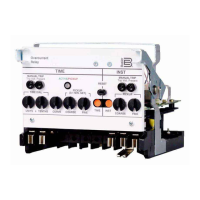
Figure 2-1. Location of Controls
and Indicators ........................................................................................ 2-1
Figure 2-2. Location of SW3 and Auxiliary Output Jumper Terminations................................................. 2-2
Tables
Table 2-1. BE1-50/51B Controls and Indicators (Refer to Figures 2-1 and 2-2)
....................................... 2-3
www . ElectricalPartManuals . com

 Loading...