4-4 BE1-50/51B Installation 9252000991 Rev N
4.03
4.03
.31
.75
6.19
(19.1)
(7.9)
(102.4)
(102.4)
(157.2)
10-32 SCREWS
MOUNTING PANEL
.25
(6.4)
AA
5/16-18 STUD
2 PLACES
TERMINAL EXTENSION (TYP.)
FOR DETAILED INSTRUCTIONS.
SEE THE TERMINAL PROJECTION
MOUNTING KIT SUPPLIED.
MOUNTING PANEL
(62.48)
2.195
(55.75)
(49.53)
1.95
2.40
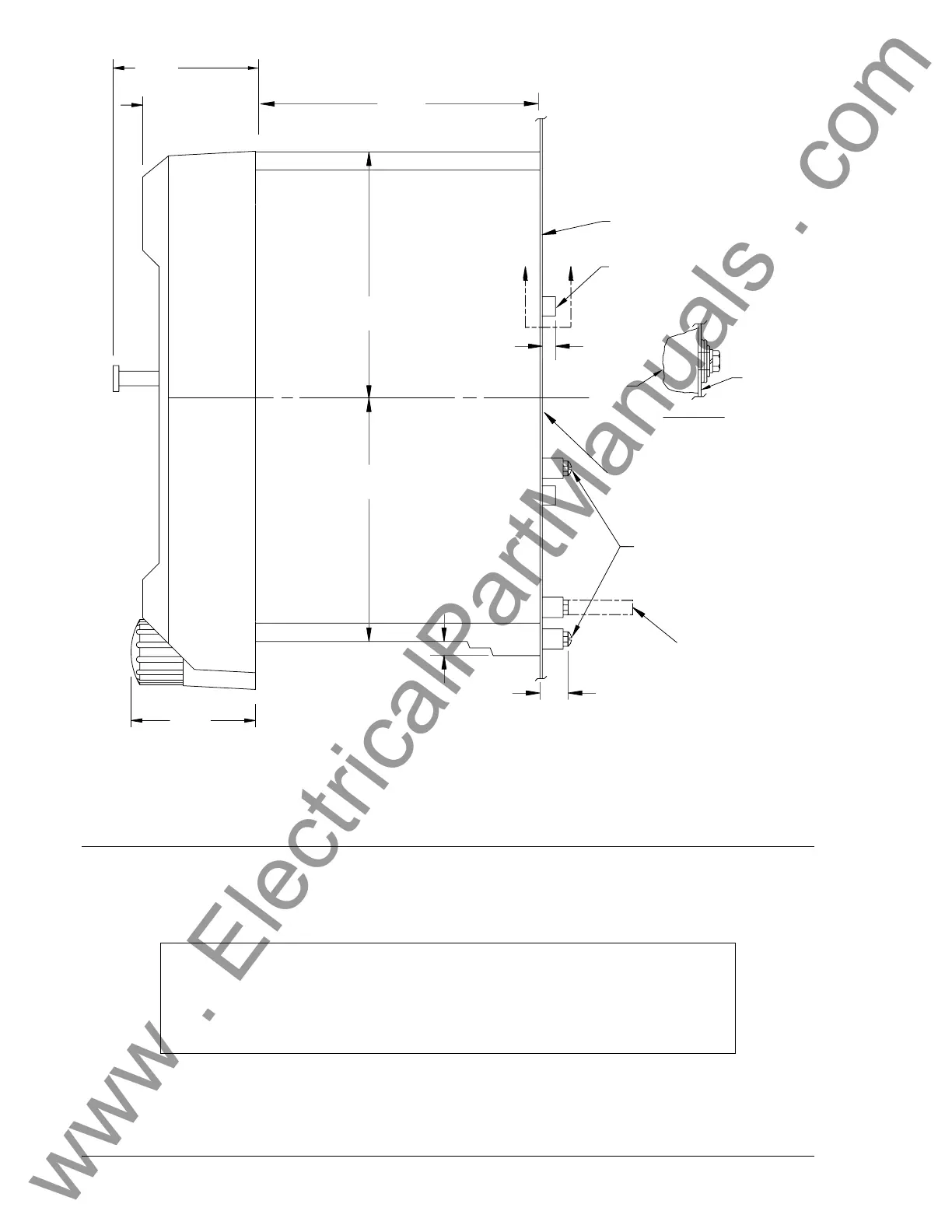
DETAIL A-A
SHOWING THE ADDITION OF WASHERS
OVER THE BOSS TO TIGHTEN THE
RELAY AGAINST THE PANEL.
CASE
PANEL
12-17-99
D2750-25
Note: Projection mount uses washers over the bosses as shown in this illustration.
Figure 4-6. Outline Dimensions, S1 Case (Projection Mount)
CONNECTIONS
Incorrect wiring may result in damage to the relay. Be sure to check model and part number before
connecting and energizing a particular relay.
Connections should be made with minimum wire size of 14 AWG except as noted for the ground wire.
Typical ac input and dc control connections are shown in Figures 4-7 and 4-8. The auxiliary output jumper
configuration schematic diagram is also shown in Figure 4-8. Relay internal connections are shown on
the back of the relay. Figure 4-9 shows a rear view of the relay and the connections.
NOTE
Be sure that the relay is hard-wired to earth ground with no smaller than 12 AWG
copper wire attached to the ground terminal on the rear of the unit case. When
the relay is configured in a system with other devices, it is recommended to use a
separate lead to the ground bus from each unit.
www . ElectricalPartManuals . com
 Loading...