EasyManua.ls Logo

Basler MVC 300 User Manual

Basler MVC 300
13 pages
To Next Page IconTo Next Page
To Previous Page IconTo Previous Page
Page #12 background image
4
-
1
A periodic inspection should be made of the unit to insure it is clean and free from accumulations of
dust and moisture. Verify that all terminal connections of the MVC-300 and the voltage regulator are
tight.
In the event of failure/defective operation of the unit, Table 4-2 provides information to determine the
probable cause of the malfunction and the solution. Refer to Paragraph 3-3 and to Figure 3-4 for the
bench test procedure.
Due to a protective coating, repair/replacement of individual components on the printed circuit board
assembly should not be attempted and the complete replacement of the board is recommended.
When ordering replacement parts from Basler Electric always specify the part number, the quantity
and the description of the item.
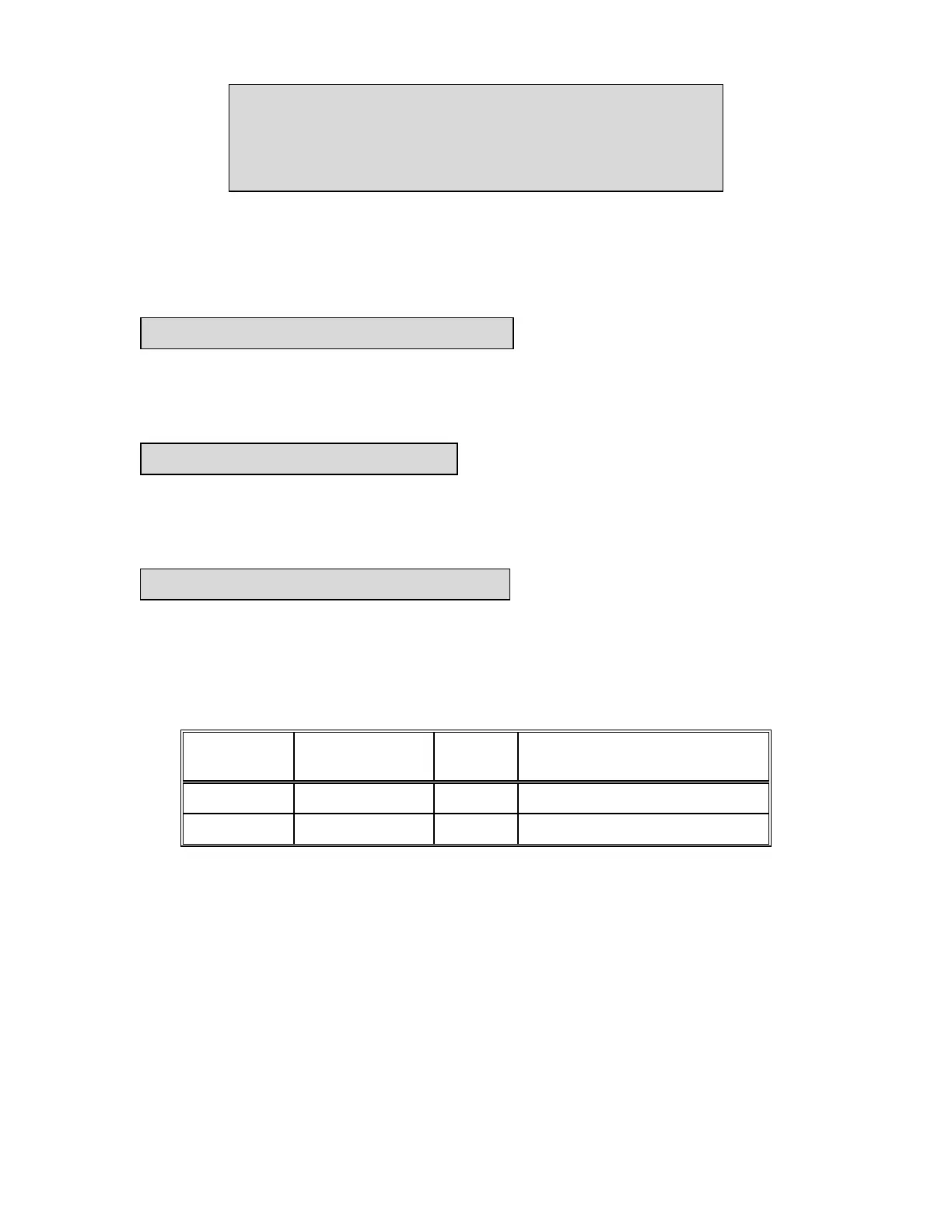
Table 4-1. Replacement Parts List.
Reference
Designator
Part
Number Quantity Description
---------------- 9 1210 01 103 1 Printed Circuit Board Assembly
F1,F2 04592 2 Fuse, 10 A, 250 V
SECTION 4
MAINTENANCE AND TROUBLESHOOTING
4-1. PREVENTIVE MAINTENANCE
4-2. TROUBLESHOOTING
4-3. RECOMMENDED SPARE PARTS
Question and Answer IconNeed help?

Do you have a question about the Basler MVC 300 and is the answer not in the manual?

Basler MVC 300 Specifications

General IconGeneral
Sensor TypeCMOS
InterfaceGigE
Shutter TypeGlobal Shutter
Lens MountC-Mount
Bit Depth8, 10, 12
Operating Temperature0°C to 50°C

Summary

SECTION 1 GENERAL INFORMATION

1-1. PURPOSE

Explains the MVC-300 as a back-up control device for voltage regulator failure.

1-2. OVERALL DESCRIPTION

Describes the MVC-300 as a solid-state, through-the-panel mounted device with front panel controls.

1-3. SPECIFICATIONS

Provides the electrical and physical specifications of the MVC 300.

SECTION 2 PRINCIPLES OF OPERATION

2-1. GENERAL

Details the MVC-300 as an SCR bridge, its startup operation, mode switch, and voltage sources.

SECTION 3 INSTALLATION AND OPERATION

3-1. INSTALLATION

Covers through-the-panel mounting, detachable front panel, and remote control options.

3-2. OPERATION

Explains operating modes (MANUAL, AUTOMATIC, OFF) and voltage build-up.

3-3. OPERATIONAL TEST

Provides a procedure for bench testing the MVC-300 using a light bulb and specific connections.

SECTION 4 MAINTENANCE AND TROUBLESHOOTING

4-1. PREVENTIVE MAINTENANCE

Recommends periodic inspection for cleanliness and tight terminal connections.

4-2. TROUBLESHOOTING

Offers information to determine the cause and solution for unit malfunction or defective operation.

4-3. RECOMMENDED SPARE PARTS

Suggests replacing the PCB assembly and lists available parts like fuses.