-
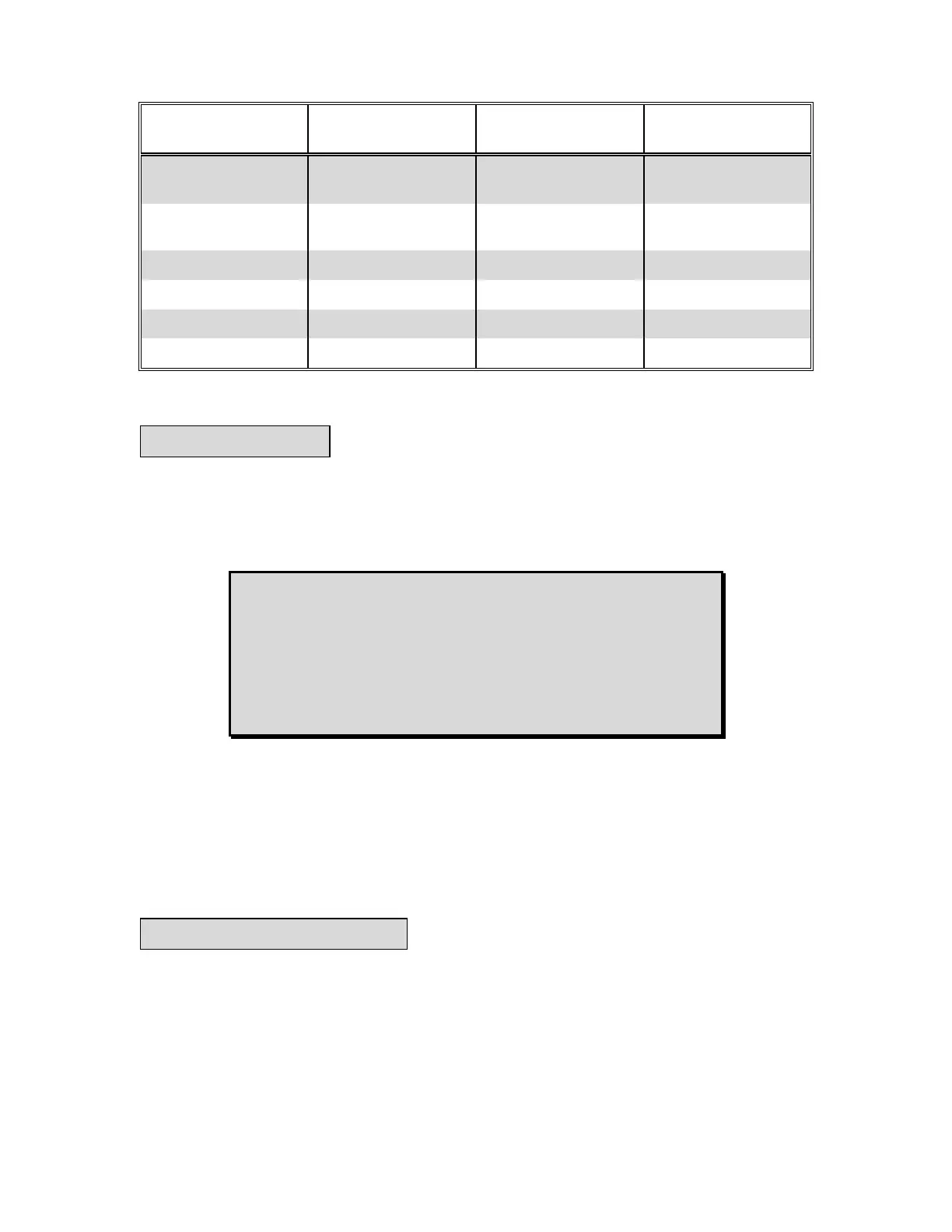
Table 3-1. Voltage Selection Chart.
Voltage Regulator
Model
Voltage Regulator
Rating
MVC Input
Voltage
Voltage Selection
Terminal
KR7F,KR7FF,
SR8A,SR8F
125 V @ 7 A or less 240 Vac 125
SR4A,SR4F,
KR4F,KR4FF
63 V @ 7 A or less 120 Vac 63
XR2001,XR2004 63 V @ 7 A or less 240 Vac 63
KR2F,KR2FF 32 V @ 7 A or less 120 Vac 32
APR63-5 63 V @ 7 A or less 240 Vac 63
APR125-5 125 V @ 7 A or less 240 Vac 125
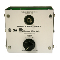
a. With the AUTO-OFF-MANUAL voltage control mode switch placed in MANUAL, the automatic
voltage regulator is removed from the line and generator output voltage is controlled manually by the
MANUAL VOLTAGE ADJUST control. When placed in the AUTOMATIC position, the generator
output voltage is controlled by the automatic voltage regulator. Complete excitation shutdown occurs
when the voltage control mode switch is placed in the OFF position.
b. Start the prime mover following the manufacturer's procedure, set the MANUAL VOLTAGE
ADJUST control to minimum (counter-clockwise), and place the AUTOMATIC-OFF-MANUAL
voltage control mode switch in MANUAL position. Note that the voltage may be unstable (hunting) if
the MANUAL VOLTAGE ADJUST control is set below 30 Vac.
c. Allow the generator to build-up and slowly increase the generator output voltage with the MANUAL
VOLTAGE ADJUST control until the generator output voltage reaches the desired level.
To verify that the MVC-300 is operating properly, use the following procedure and the connections of
Figure 3-4 for a bench test. Notice that the voltage regulator is not necessary for this test.
(1) With no power applied to the MVC-300 and all connections to the voltage regulator re-
moved, place the AUTO-OFF-MANUAL voltage control mode switch to the MANUAL posi-
tion.
(2) Connect a 120 Vac 100 Watt light bulb to terminals F+ and F- of the MVC-300, and connect
the jumper to Terminal 63.
3-2. OPERATION
CAUTION
With the voltage control mode switch in either MANUAL or OFF
position, some terminals of the regulator are connected to the
generator and present a potential shock hazard. No attempt
should be made to remove or troubleshoot the regulator while
the generator is running.
3-3. OPERATIONAL TEST