Purification Systems
Page 11 3rd Edition, Rev 0 Chg 6
CHAPTER 3: SINGLE CHAMBER PURIFICATION SYSTEMS
3.1 Applicability
This chapter applies to Bauer Purification Systems P0 and P31 Only.
3.2 P0 Purification System Description
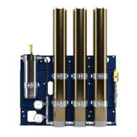
The P0 Purification System consists of a separator and a cartridge chamber. In the separator surround-
ing the cartridge chamber, liquid oil and water particles are separated from the compressed air by a pipe
nozzle. Residual oil and water particles are then removed by the filter cartridge and the air leaving the
P0 Purification System is free of water, oil, taste and smell.
Figure 3-1 P0 Purification Chamber
1. Inlet Connection
2. Condensate Drain Connection
3. Condensate Drain Valve
4. Bleed Port
5. Bleed Valve
6. Pressure Maintaining Valve
7. Outlet Connection
8. Safety Valve