Do you have a question about the Bauer Compressors UNICUS 4i - 25 and is the answer not in the manual?
Guidance on using the manual, including safety notices and best practices.
Instructions for locating and ordering replacement parts from the manual.
Information on accessing and utilizing the appendix content for reference data.
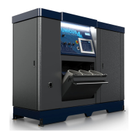
Detailed technical specifications for the UNICUS 4i - 25 model, including block and drive.
Identification and description of major components on the unit.
Instructions for the emergency stop button function and operation.
Overview of the touchscreen interface, including the badge screen for access.
Managing personnel records, including adding, editing, and deleting users.
Managing cylinder records, including adding, editing, and deleting.
Configuration options for system setup, parameters, and maintenance.
Viewing operational reports and using diagnostic tools for troubleshooting.
The primary operator screen displaying system status and controls.
Viewing compressor status and procedures for filling air cylinders.
Using the remote fill option for cylinder filling.
Step-by-step guide for operating the fill station to fill bottles.
Detailed steps for connecting air bottles, filling them, and disconnecting.
Overview of the compressor block, its design, and component locations.
Diagram illustrating the air flow path through the compressor stages.
Details on the lubrication system, oil levels, changes, and intervals.
Procedure for venting the oil pump after maintenance or incorrect rotation.
Description and maintenance of the intake air filter and its service indicator.
Description and maintenance of the 2nd, 3rd, and 4th stage interstage separators.
Details on the function and types of compressor valves and valve heads.
Checking valve operation and general instructions for changing valves.
Step-by-step procedure for changing the 1st stage compressor valves, including removal and installation.
Step-by-step procedure for changing the 2nd stage compressor valves, including removal and installation.
| Brand | Bauer Compressors |
|---|---|
| Model | UNICUS 4i - 25 |
| Category | Air Compressor |
| Language | English |