
B
Benjamin WallaceAug 2, 2025
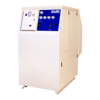
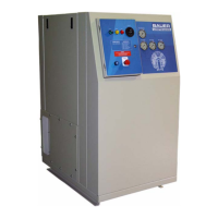
Why is my Bauer Compressors Air Compressor running too hot?
- WwilsonmarthaAug 2, 2025
If your Bauer Compressors Air Compressor is running too hot, it could be due to several reasons. First, ensure that the location has adequate ventilation to supply sufficient cooling air. Second, check and clean the intake or outlet valves, replacing them if necessary. Finally, verify the compressor's rotation direction matches the arrow and correct it at the switch box if needed.