Page 6 For technical questions, please call 1-888-866-5797. 57287
SAFETY OPERATION MAINTENANCESETUP
Specifications
Electrical Rating 120VAC / 60Hz / 4.8A
Motor No Load Speed 3,600 RPM
Max. Accessory Diameter 8″
Arbor Size 5/8″
Setup - Before Use:
Read the ENTIRE IMPORTANT SAFETY INFORMATION section at the beginning of this
manual including all text under subheadings therein before set up or use of this product.
TO PREVENT SERIOUS INJURY FROM ACCIDENTAL OPERATION:
Turn the Power Switch of the tool off and unplug the tool from its electrical outlet
before performing any procedure in this section.
Note: For additional information regarding the parts listed in the following pages,
refer to the Assembly Diagram near the end of this manual.
Assembly/Mounting
The two mounting holes in the Base can be used
to attach this Grinder to a stable workbench
using appropriate hardware (sold separately).
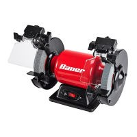
1. Install Right Work Rest Support (57) to the
Right Inner Wheel Guard (21). Use two
Hex Bolts (12) and two Flat Washers (13)
to secure it in place. See below.
Work Rest
Support (57)
Hex
Bolt (12)
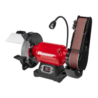
2. Install Right Work Rest (41) to the Right
Work Rest Support using Washer (8) and a
Work Rest Locking Knob (14). See below.
Work Rest (41)
Washer (8)
Locking
Knob (14)
Work Rest
Support (57)
3. Install Left Work Rest Support (56) to the Left Inner
Wheel Guard (6). Use two Hex Bolts (12) and
two Flat Washers (13) to secure it in place.
4. Install Left Work Rest (58) to the Left
Work Rest Support using Washer (8)
and a Work Rest Locking Knob.
5. Adjust the Work Rests to within 1/16″ of the
Grinding Wheel. To adjust this distance,
loosen Bolts (12) and move Work Rests (41/58).
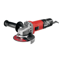
6. Attach a Spark Guard (46,47) to each
Inner Wheel Guard (21,6) using two
Bolts, Spring Washers, Flat Washers (45)
on each side. See below.
Spark
Guard (46)
Inner Wheel
Guard (21)
Bolt (45)
7. Adjust each Spark Guard (46,47) to within
1/16″ (0.0625″) of the Grinding Wheel
and tighten each Bolt (45).
8. Attach the Eye Shield (11) to the Right
Spark Guard (46) using a Neck Screw (48), Eye
Shield Locking Knob (7) and Flat Washer (8).
9. Attach the other Eye Shield (11) to the Left
Spark Guard (47) using a Neck Screw (48), Eye
Shield Locking Knob (7) and Flat Washer (8).