Page 10 For technical questions, please call 1-888-866-5797. Item 58871
SAFETY OPERATION MAINTENANCESETUP
7. For wheels with paper gaskets (blotters) or
metal gaskets: Slip the grinding wheel onto the
Spindle with the gasket first. The gasket should be
centered on the grinding wheel and the wheel and
gasket should rest flat against the Inner Flange.
WARNING: To prevent serious injury, gaskets
must be used for all grinding wheels they are
provided with. Gaskets help prevent grinding
wheel damage and wheel slippage,
causes of wheel failure.
8. Install the new grinding wheel and place the
Outer Flange in position on the Spindle.
9. Thread the M16 Lock Nut onto the Spindle.
Wrench tighten only enough so that the
wheel is securely held on the Spindle.
WARNING: To prevent serious injury, do
not overtighten Lock Nut. Overtightening can
damage the wheel, causing wheel failure.
10. Replace the Wheel Guard Cover and secure
in place using the three M5 x 46 Screws.
Setting and Testing
TO PREVENT SERIOUS INJURY FROM ACCIDENTAL OPERATION:
Make sure that the Power Switch is in the off-position and unplug the tool from
its electrical outlet before performing any procedure in this section.
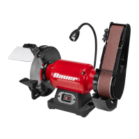
Adjusting Sanding Belt Tracking
1. Turn the Grinder/Belt Sander on,
then immediately turn off.
2. The Belt should remain centered on the front
and rear Drums. If the Belt starts moving to the
side of either Drum, it needs to be adjusted.
3. If the Belt moves towards the outside
of the Sander, turn the Belt Alignment
Knob slightly counterclockwise.
4. If the Belt moves towards the inside of the Sander,
turn the Belt Alignment Knob slightly clockwise.
5. Turn the Grinder/Belt Sander on and immediately
off again after adjustment to check alignment.
6. If necessary, continue to adjust the Belt
Alignment Knob until the Belt rides
in the center of both Drums.
Belt
Alignment
Knob
Changing Sanding Arm Position
The Sanding Arm can be used in a horizontal
or vertical position or at any angle in‑between
from 0 to 90 degrees. To change the
Sanding Arm position, do the following:
1. Loosen the two M5 x 12 Cap Screws as
shown and raise the Sanding Arm to
the desired vertical position/angle.
2. After positioning, wrench tighten the two Cap Screws
securely to prevent the Sanding Arm from slipping.
Sanding
Arm
M5x12
Cap Screw