Baumer_TD3A4KA_OI_DE-EN_1606.indd 11
5. Mechanical Mounting
5.1. Preparations
• Attention!Observethesafetyinstructionsinchapter4.
• Make sure the drive will not be operational for the time of tachogenerator
installation.
• Prior to any installation work, switch off overall voltage supply and ensure
machinery is idle..
• Werecommendsufcientcontactsurfaceaccordingtothedimensionsspeciedin
chapter8.Fortachogeneratortypeidenticationseeproductlabel.
• Prior to installation, make sure any motor parts protruding into the tachogenerator
are clean and free from lubricants or oil. Lubricants or oil heating up may affect the
collector and cause voltage drops, worse residual ripple, lamella short-circuiting or
groove formation with severe carbon abrasion.
5.2. Installation
• Makesurethenecessarypreparationsforinstallationaccordingto
chapter 5.1. are present.
1. Slide rotor onto drive shaft.
Important: Rotor must smoothly slide along drive shaft, do not apply force.
Neveruseahammer.Wheretistight,useatoolsupportedbythesteelhollow
shaft in order to prevent the rotor from getting jammed.
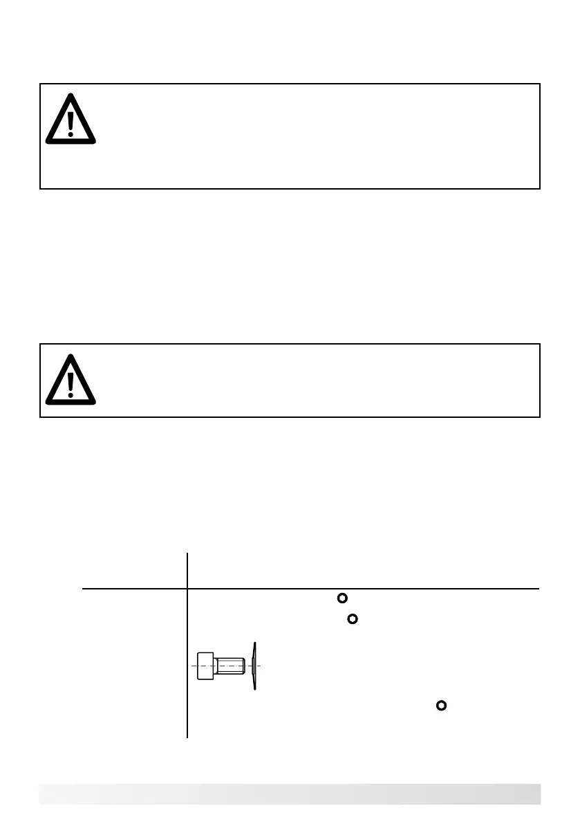
2. Observe dimension „b“ . See dimensional drawings in chapter 8. (b = 17+1).
3. Secure tachogenerator onto drive shaft using the screws according to drawing (see
dimensional drawing). Observe the tightening torques of the mounting screws.
Rotor (pole
wheel)
Mounting type, screw/pin, tightening torque
Type KM
Clamping connection, M4,
A/F 2.5 resp. A/F 3.0; 1.8 Nm
Type AM
Axial screw connection, M5,
A/F 4; 4.5 Nm;
use disc spring
Type RM
Radiale screw connection, mounting pin M5,
A/F 2.5; 4.5 Nm
Type SM Mounting pin, M4, by customer