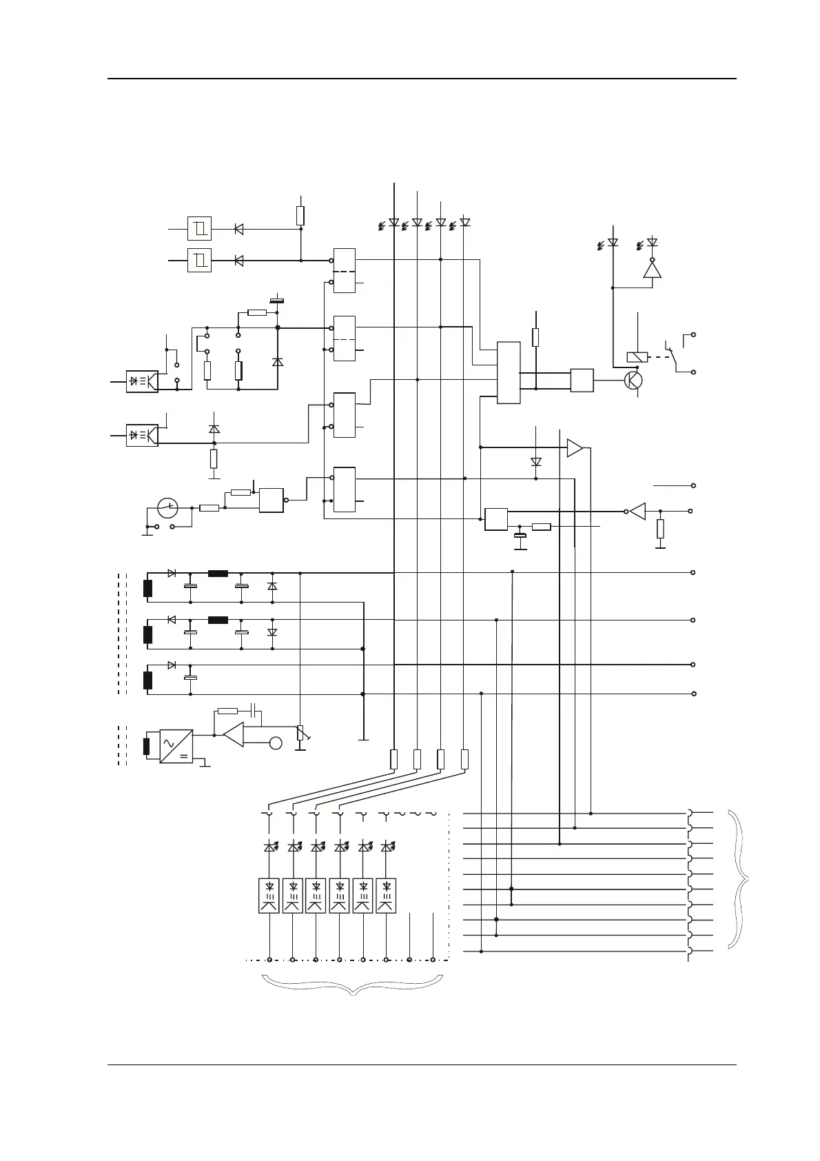
Function diagram Commissioning
BUG 3/2/20 Basic Feed Unit 45
Baumüller Nürnberg GmbH 5.96064.02
W201: fitted with external ballast
W202: fitted with BUG 2/3 (t = 1.5 s)
W203: fitted with BUG 20 (t = 1.8 s)
+15 V
(SELV)
-15 V
(SELV)
L with
10% dev.
Error store
++
S
S
S
S
R
R
R
R
Q
Q
Q
Q
Q
Q
Q
Q
LED H204 ... 206 with BUG 20 only
H204 red: t > x s
ballast
H203 red: U > 400 V
ZK
H205 red: +/- 15 V not OK
H206 red: Temp. > 72° C
H202 green: ready-for-use system
H201 red: system error
X1:7 (SELV)
X1:8
X1:2
X1:1
X1:4
+15 V (SELV)
-15 V (SELV)
+24 V (SELV)
BSa (SELV)
X1:5
X1:6
X1:3
+24 V
Clear memory
&
&
Contact closed
on ready-for-use
&
Switch-on
reset
W202
W203
W201
L: Uzk > 400 V
L: t > x
Te mp .
switch
W204
&
L: Temp. > 92° C
(BUG 2)
T1
+15 V
+24 V
Ground
T2
BSs
-15 V
PAM
U controller
1
23
4
6789
10
+10 V
-15 V -10 V M +15 V
Test adapter BU: Connect via connector
on the bottom of the device
H1 red - not
connected
H1 red - not
connected
H3 red TKK temperature
of power unit too high
H4 red +/- 15-V supply
voltage not correct
H5 red Uzk intermediate circuit
voltage > 400 V
H6 red TB ballast resistor
overloaded
H6
UU
H5 H4 H3 H2 H1
System bus X9
SLS - Clear memory SLS
BBS - Ready-for-use system BBS
RFS - Controller enable system RFS
Res+
Res-
+15 V +15 V
+15 V
-15 V -15 V
-15 V
BSa, BSn - Reference potential analog or n controller BSa, BSn
10
9
8
7
6
5
4
3
2
1
7
65
4
3
21
0
X27
s
s
+
++
+
+
+
+
-
+
=
(SELV)
(SELV)
(SELV)
SELV
SELV