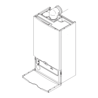
4 Description of the product
20 Combi 2
Fig.6 Schematic diagram
4.3 MAIN COMPONENTS
Fig.7 Functional diagram
4.2.4 Schematic diagram
Plate heat exchanger (DHW)
Motorised three-way valve
1. Construction
2. Hooks for fastening the bracket to the wall
3. Flue gas tower
4. Expansion vessel air control/filling valve
5. Expansion vessel
6. Hydraulic circuit-expansion vessel connection pipe
7. Air-gas collector
8. Fan (air-gas assembly: Control board and mixer valve)
9. Heating return sensor
10. Gas valve
11. Heating system and pump venting valve
12. Pump
13. Cable gland
14. Control panel with boiler PCB and display
15. Domestic hot water plate heat exchanger fastening screws
16. Domestic hot water priority sensor
17. Domestic hot water plate heat exchanger
18. Siphon
19. Hydraulic safety valve (3 bar)
20. Hydraulic pressure gauge
21. 3-way valve
22. Air-gas silencer assembly
23. Heating circuit water flow sensor (°C)
24. Safety thermostat (limit)
25. Condensate drain pipe connection towards discharge
26. Detection/ignition electrode
27. Burner flange
28. Flue gas temperature sensor
29. Boiler earthing socket
BO-7746442
12
 Loading...