33
10.0 Installation
© Baxi Heating UK Ltd 2012
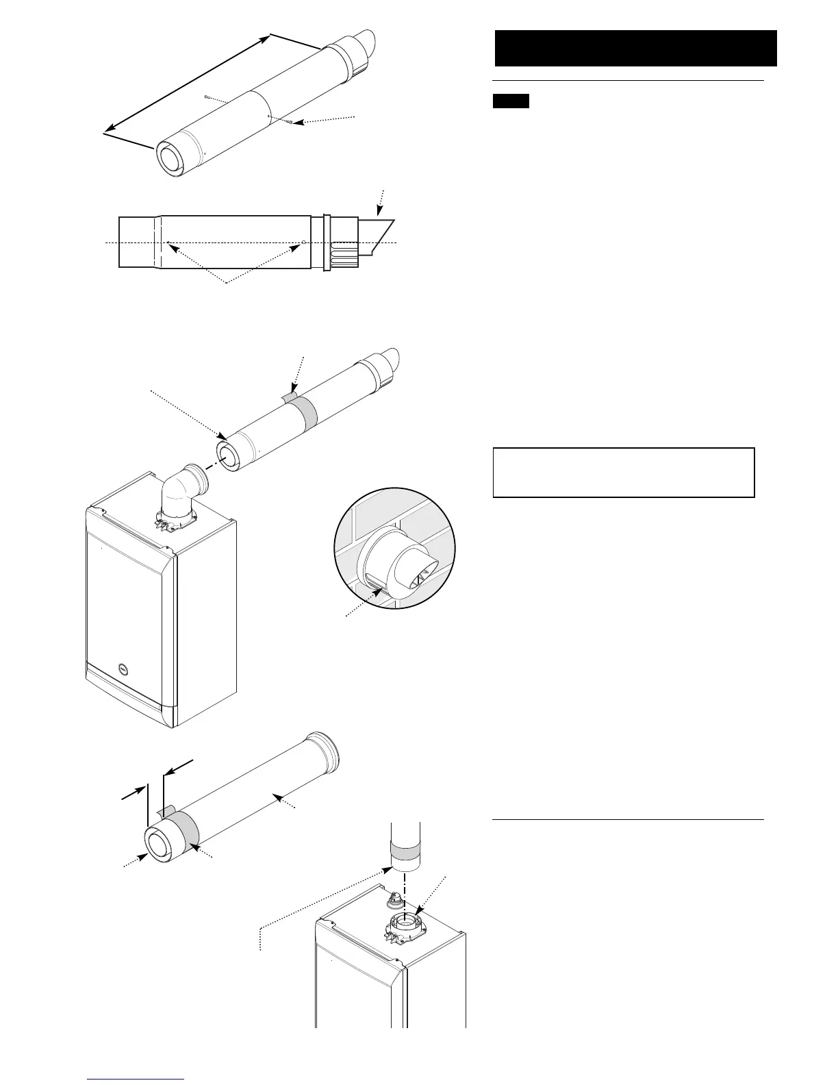
10.6 Fitting the Flue (Cont)
8. Adjust the two telescopic sections to dimension ‘Y’
(Fig. 41). Ensure that the rivets and holes in the Connection
Assembly are aligned horizontally (Fig. 42).
9. Using a 2mm bit, drill through the holes at the end of the
Connection Assembly into the Terminal Assembly and
secure them together using the screws supplied (Fig. 41).
Seal the joint with the tape provided (Fig. 43).
10. Remove the flue elbow and insert the flue through the
hole in the wall. Refit the elbow to the boiler adaptor,
ensuring that it is pushed fully in (Fig. 40).
11. Draw the flue back through the wall and engage it in
the elbow. It may be necessary to use soap solution or
similar to ease assembly of the elbow adaptor and flue
(Fig. 43).
12. Ensure that the terminal is positioned with the slots to
the bottom (Fig. 44).
IMPORTANT: It is essential that the flue terminal is fitted
as shown to ensure correct boiler operation and prevent
water entering the flue.
13. Make good between the wall and air duct outside the
building.
14. Fit the flue trim if required, and if necessary fit a terminal
guard (see Section 8.8 & 8.9).
CONCENTRIC VERTICAL FLUE
15. Once the length of the vertical concentric extension has
been determined mark and carefully cut off the excess
material. The cut end MUST be square and free of burrs to
ensure correct insertion into the boiler adaptor.
16. Measure 25mm from the end of the flue extension and
apply a length of tape around the outer duct (Fig. 45).
17. Engage the extension into the adaptor up to this
position (Fig. 46). Once the installation of the flue is
complete and all support brackets are securely in place
remove the tape.
Slots at bottom
Fig. 42
Fig. 43
Fig. 44
Apply Lubricant for
ease of assembly.
Ensure Flue is fully
engaged into Flue
Elbow
Sealing Tape
‘Peak’ to be uppermost
Rivet & Hole to be
aligned on horizontal
centreline
Dimension ‘Y’
Securing Screw
Fig. 41
Adaptor
Apply Lubricant for
ease of assembly.
Ensure Extension is
fully engaged into
Boiler Adaptor
25mm
Extension
Cut End
Fig. 45
Tape
Fig. 46
 Loading...