8
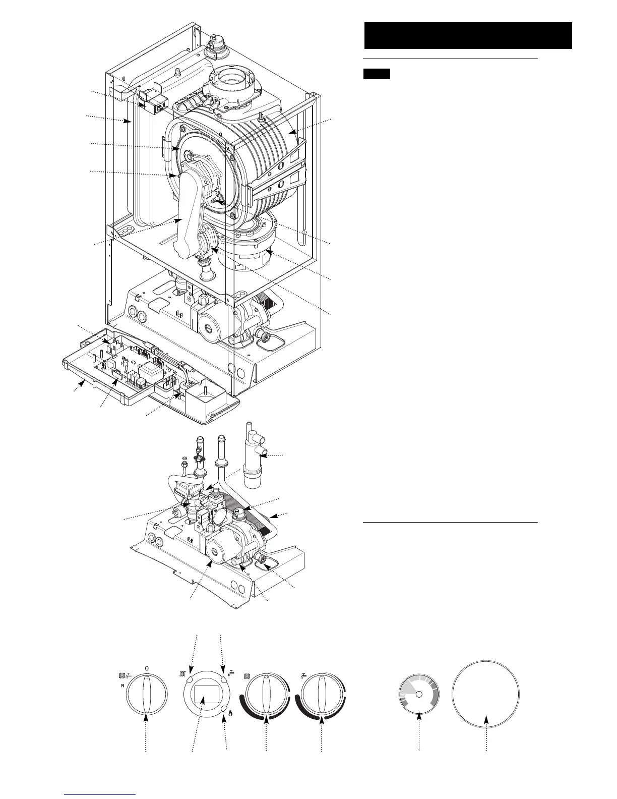
2.0 General Layout
© Baxi Heating UK Ltd 2012
2.1 Layout
1. Expansion Vessel
2. Automatic Air Vent
3. DHW Plate Heat Exchanger
4. Circulation Pump
5. Drain Off Point
6. Pressure Relief Valve
7. Selector Switch
8. Central Heating System Pressure Gauge
9. PCB
10. Control Box
11. 3-Way Valve Assembly
12. Condensate Trap
13. Flame Sensing Electrode
14. Spark Electrode
15. Primary Heat Exchanger
16. Fan Assembly
17. On/Off/Reset Selector Switch
18. Central Heating Temperature Control
19. Hot Water Temperature Control
20. Venturi
21. Air/Gas Collector
22. Combustion Box Cover & Burner
23. Igniter
24. Burner On Light
25. Central Heating Mode Light
26. Domestic Hot Water Mode Light
27. Display
28. Position of Optional Integral Timer
1
17
18
19
8
 Loading...