5
Electric connection of additional functions
The following installation instructions provide an overview of the various connection options. Here, various examples
are used to illustrate how the Smart&Easy Control Module is connected to the various electronic components.
Important:
It must be ensured that all safety regulations are complied with during the electrical installation and that all component-
specic connection specications are observed! To do this, carefully read the operating instructions of the devices to
be connected and compare them with the technical data of the Smart&Easy Control Module.
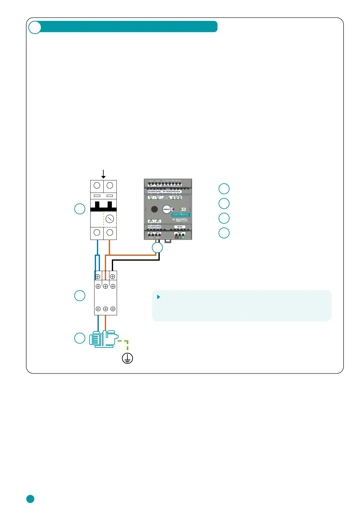
5.1 Single Speed Filter Pump (ON/OFF)
The connection of a lter pump with a xed speed can be carried out according to the following wiring diagram.
The use of an appropriate contactor and motor circuit breaker is compulsory.
1
2
3
4
Motor Circuit Breaker
Contactor
Filter Pump
Connection to OUT 1 – 4 possible
Hint
By using a contactor, the hardware of the Smart&Easy Control
Module is protected by separating the control and main circuits.
1
2
230 V AC + RCD (≤ 30 mA)
4
3
A1
1
2
3
4
5
6
L1
T1 T2
L2 L3
T3
A2
24