4
Installation
– The installation of the Smart&Easy Control Module must be carried out by authorised and trained professionals
(electricians).
Warning: Danger to life
– Mounting on DIN rail (DIN rail according to EN 50022)
– Ensure good accessibility and visibility
– Protection against water and dust (control cabinet)
– Ensure sufcient signal strength for Automatic! Signal status is displayed during the connection process!
– Electrical installation must be protected by a Residual Current protective Device (RCD) ≤ 30 mA, according to
local regulation
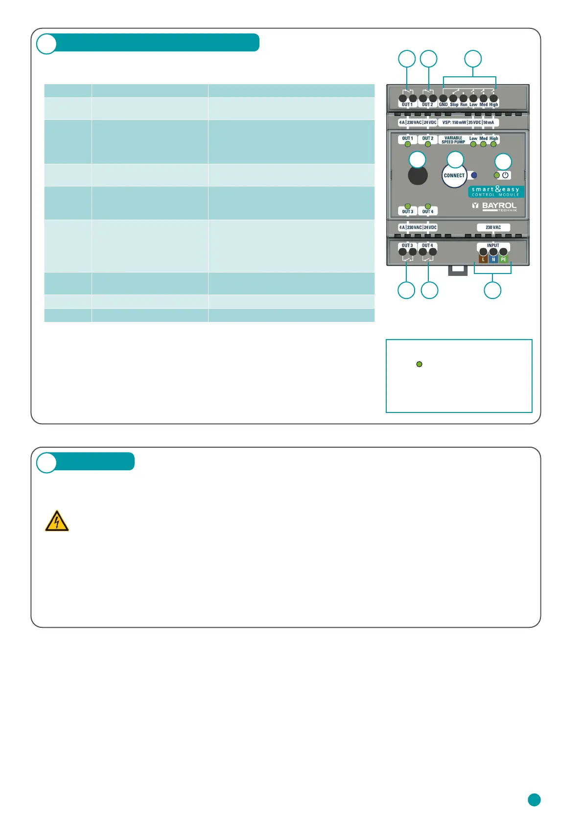
The following table describes the connections and indicators:
3
Connections & Specications
Important:
The device is powered by 230 V AC. Potential-free relays are used for the
outputs OUT 1 – 4. These relays do not supply the connected equipment with
230 V AC. An external power supply, protected by the component-specic
fuses, is required for these.
1 2
3 4 6
5
7 8
9
Number Designation Property
1, 2, 3, 4
Relay switching outputs:
OUT 1 – 4
4 x NO relays, potential-free
4 A / 230 V AC / 24 V DC
5
Variable Speed Pump (VSP)
outputs
4 x Digital Relays:
– 3 x NO: Eco, Normal, High
– 1 x NO/NC: Stop/Run
150 mW / 35 V DC / 50 mA
6 Power supply 230 – 240 VAC (L, N, PE)
50 – 60 Hz
7
Antenna Connector
WIFI, 2.4 GHz
1-1 pairing only with automatic device.
Antenna with screw thread
8 Blue LED
Establishing a connection / pairing with
Automatic
– Fast flashing = device pairs
– Permanenetly on = connection available
– Slow Flashing = Trying to reconnect
9 Green Power LED (ON/OFF)
LED lights = Smart&Easy Control Module
is switched on.
10 Power consumption max. 5 W
11 Dimensions incl. antenna 70 x 90 x 80 mm
Via the respective green status
LEDs
on the top side of the
Smart&Easy Control Module the
operating status is displayed.
Green LED lights up = active
23
 Loading...