Bayside Megara Fan Installation Instructions
6 | P a g e v 1 . 0 ( 0 3 / 2 0 2 0 )
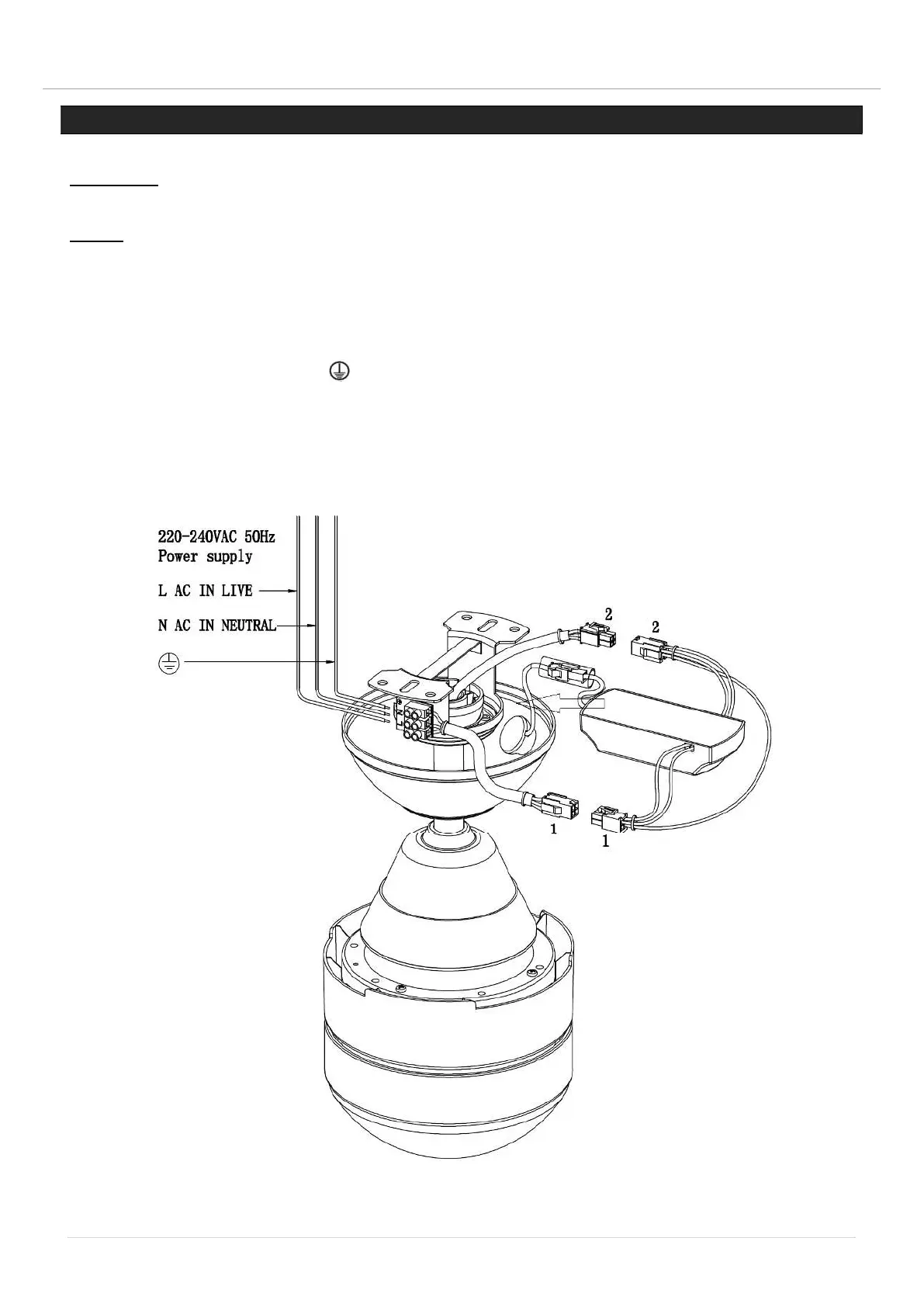
ELECTRICAL WIRING DIAGRAM
WARNING: FOR YOUR SAFETY ALL ELECTRICAL CONNECTIONS MUST BE UNDERTAKEN BY A
LICENSED ELECTRICIAN.
NOTE: AN ADDITIONAL ALL POLE DISCONNECTION SWITCH MUST BE INCLUDED IN THE FIXED
WIRING.
Connect “LIVE” supply wire to the “L” of terminal block on the mounting bracket.
Connect “NEUTRAL” supply wire to the “N” of terminal block on the mounting bracket.
Connect “EARTH” wire to the “ ” of terminal block on the mouthing bracket.
Insert the receiver into the mounting bracket and onto the ball joint.
Connect the output connector (1) from the receiver to the connector (1) from the fan body.
Connect the connector (2) from the fan mounting bracket to the input connector (2) from the receiver.
Fig. 7