28
4. MESSA IN FUNZIONE (BF)_P3 11-16 rev. 0
4.4
IT
IT
Fissare la parte posteriore della protezione A al gruppo
manovellismo come indicato nelle figure 4/3 e 4/4 in fun-
zione del tipo di manovellismo e del gruppo motore.
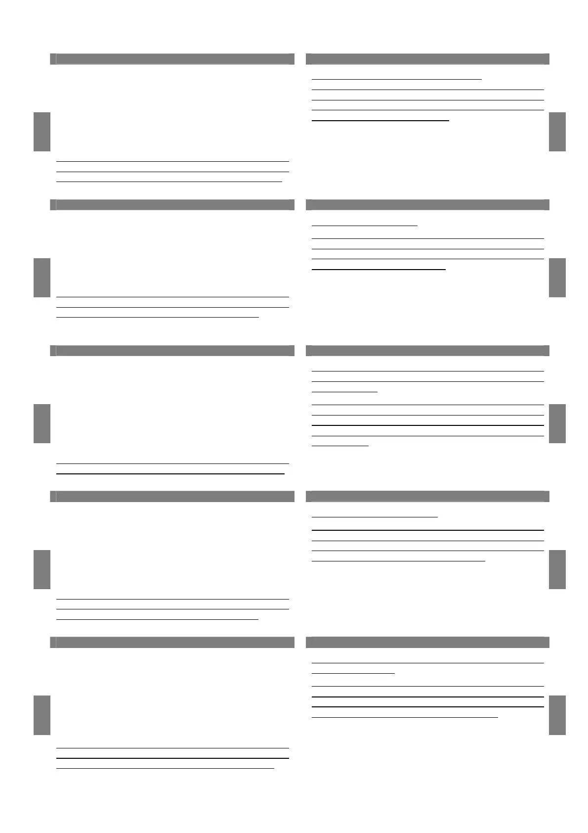
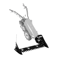
4.4 Assemblaggio della barra falciante al gruppo ma-
novellismo
Appoggiare la barra falciante in piano e rimuovere i due
dadi D e le relative rondelle (fig.4/5 e 4/6).
Avvicinare il gruppo manovellismo alla barra falciante fa-
cendo attenzione che il perno entri nella sua sede quindi
montare la barra falciante B al gruppo comando A con i 2
dadi D e le rondelle (fig.4/6) e serrare forte.
N.B. Per il montaggio del gruppo falciante DUPLEX e
DUAL Laser (a doppia manovella) prestare attenzione che
entrambi i perni F e G entrino nella loro sede (fig.4/7),
quindi procedere come detto sopra.
SE E’ NECESSARIO FARE UN TAGLIO DELL’ERBA AL-
TO, PROCEDERE COME SEGUE: montare le slitte di re-
golazione altezza di taglio C sulla barra falciante con le viti
in dotazione (fig.4/8a e 4/8b).
4.4
EN
EN
Fix the rear side of protection A to the transmission, as
shown in figures 4/3 and 4/4 according to the type of tran-
smission and gearbox.
4.4 Assembly of the cutter bar to the transmission
Lay the cutter bar flat and remove the two nuts D and rela-
ted washers (fig.4/5 and 4/6).
Move the transmission closer to the cutter bar making sure
that the pivot is correctly lodged then mount the cutting bar
B to control panel A by the two nuts D and washers
(fig.4/6) and tighten hardly.
N.B. For the assembly of the DUPLEX and DUAL Laser
mowing group (with a double crank mechanism), make
certain both pins F and G fit into their housings (fig.4/7),
then proceed as described above.
IF NECESSARY CUT HIGH: install the cutting height ad-
justment slides C on the cutter bar using the bolts provided
(fig.4/8a and 4/8b).
4.4
FR
FR
Fixer la partie postérieure de la protection A au groupe de
mécanisme à manivelle comme indiqué dans les figures
4/3 et 4/4 en fonction du type de mécanisme à manivelle
ou du groupe moteur.
4.4 Assemblage de la barre faucheuse au groupe de
mécanisme à manivelle
Mettre la barre faucheuse à plat et enlever les deux écrous
D ainsi que leurs rondelles (fig.4/5 et 4/6).
Rapprocher le groupe du mécanisme à manivelle à la bar-
re faucheuse en faisant attention que l’axe entre dans son
siège. Monter la barre de coupe B au groupe de comman-
de A avec les deux écrous D et les rondelles (fig.4/6) et
serrer fortement.
N.B. Pour le montage du groupe faucheur DUPLEX et
DUAL Laser (à double manivelle), il faut faire très attention
que les deux pivots F et G entrent dans leur emplacement
(fig.4/7), par conséquent il faut procéder selon la descrip-
tion ci-dessus.
SI NECESSAIRE COUPER HAUT: monter les traineaux
réglage de la hauteur de coupe C sur la barre de coupe
avec les vis (fig.4/8a et 4/8b).
4.4
ES
ES
Fijar la parte trasera de la protección A al grupo articulado
tal y como se indica en las figuras 4/3 y 4/4 en función del
tipo de mecanismo articulado y del grupo motor.
4.4 Ensamblado de la barra de corte al grupo de meca-
nismo articulado
Apoyar la barra de corte nivelada y quitar las dos tuercas
D y las correspondientes arandelas (fig.4/5 y 4/6).
Acercar el grupo articulado a la barra de corte haciendo
que el perno entre en su sitio. Montar la barra de corte B al
grupo mando A con las 2 tuercas D y las arandelas
(fig.4/6) y atornillar fuertemente.
Nota: para el montaje del grupo de siega DUPLEX y
DUAL Laser (de doble manivela) hay que tener la precau-
ción de que los dos pernos F y G entren en su sitio (fig.
4/7) y hacer lo que se menciona más arriba.
SI SE NECESITA CORTAR ALTO: montar los patines de
regulación de altura de corte C sobre la barra de corte,
con los tornillos de la dotación (fig.4/8a y 4/8b).
4.4
DE
DE
Den hinteren Teil der Abdeckung A am Antrieb entspre-
chend Abb.4/3 und 4/4 je nach der Art des Antriebs und
des Motors befestigen.
4.4 Montage des Mähbalkens am Mähantrieb
Den Mähbalken auf einer flachen Ebene absetzen und die
beiden Muttern D und entsprechenden Unterlegscheiben
(Abb.4/5 und 4/6) entfernen.
Den Mähantrieb dem Mähbalken nähern und dabei darauf
achten, dass der Bolzen in die entsprechende Aufnahme
eingreift. Mähbalken B an Antriebsgruppe A durch zwei
Muttern D und Unterlegsscheiben montieren (Bild 4/6) und
kräftig verschrauben.
Hinweis: Beim Anbringen des Mähaggregats DUPLEX
und DUAL Laser (mit Doppelkurbel) darauf achten, dass
beide Zapfen F und G in ihre Aufnahme gesetzt werden
(Bild 4/7); daraufhin wie beschrieben vorgehen.
BEIM HOCH SCHNEIDEN: Schlitten C für den Schnitthö-
heneinstellung auf Mähbalken durch die gelieferten Schrau-
ben (Abb.4/8a und 4/8b) montieren.