A
A
A
A
B
B
1
1
2
2
3
3
4
4
A A
B B
C C
D D
100 ENTERPRISE DRIVE
PITTSBURGH, PA 15275
(800) 523-2462
TITLE:
PART NUMBER:
DRAWN BY:
CHECKED BY:
RELEASED:
DRAWING NUMBER :
BEA, INC.
4.5" Square Text Only Pushplate
10PBS45
kjgierl
4/4/2003
10PBS45
34.43[ mm]
1.36"
1
1
4
.
3
0
[
m
m
]
4
.
5
"
114.30[ mm]
4.5"
Tech Support: 1-800-407-4545 | Customer Service: 1-800-523-2462
General Tech Questions: techservices-us@BEAsensors.com | www.BEAsensors.com
Page 4 of 4 75.5940.05 PUSH PLATE FAMILY 20240315
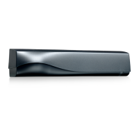
NOTE: The following accessories must be installed before securing push plate to the box:
• adapter plate (10BRINGC for double-gang boxes and 50.5016 for vestibule plates)
• weather ring (10WRSQ475, 10WRRND45, 10WRRND6)
3. For all push plates except the 4.5” square, thread each hex-head screw
3
⁄4 of the way into the electrical
enclosure. Leave about
1
⁄2” of the screw unthreaded. See note below for type of screw to use.
The 4.5” plate (see image, right) requires #6 Phillips screws for both single- and
double-gang installations. Once the back plate is secured, the face plate must be
reattached.
4. Install the push plate onto the box (see image, right), aligning the
applicable keyholes with the hex screws. Slide the push plate down,
and then secure the push plate to the box by tightening the screws
using the provided hex key.
5. Test for proper push-plate activation.
The 6” and 4.75” push plates contain 2 sizes of screws:
larger screws = corners of 4×4 electrical type boxes (A, left)
smaller screws = single/double-gang electrical boxes (B, left)
4.75” square shown here
MAINTENANCE
Clean the push plates using only a damp, non-abrasive cloth.
Regular cleaning with harsh solvents or abrasive materials may cause deterioration of the paint or coating.
MOUNTING & WIRING (cont.)
BEA, INC. INSTALLATION/SERVICE COMPLIANCE EXPECTATIONS
BEA, Inc., the sensor manufacturer, cannot be held responsible for incorrect installations or incorrect adjustments of the sensor/device;
therefore, BEA, Inc. does not guarantee any use of the sensor/device outside of its intended purpose.
BEA, Inc. strongly recommends that installation and service technicians be AAADM-certified for pedestrian doors, IDA-certified for
doors/gates, and factory-trained for the type of door/gate system.
Installers and service personnel are responsible for executing a risk assessment following each installation/service performed, ensuring
that the sensor/device system performance is compliant with local, national, and international regulations, codes, and standards.
Once installation or service work is complete, a safety inspection of the door/gate shall be performed per the door/gate manufacturer’s
recommendations and/or per AAADM/ANSI/DASMA guidelines (where applicable) for best industry practices. Safety inspections must
be performed during each service call – examples of these safety inspections can be found on an AAADM safety information label (e.g.
ANSI/DASMA 102, ANSI/DASMA 107, UL294, UL325, and International Building Code).
Verify that all appropriate industry signage, warning labels, and placards are in place.
 Loading...