100-240 VAC
Note:
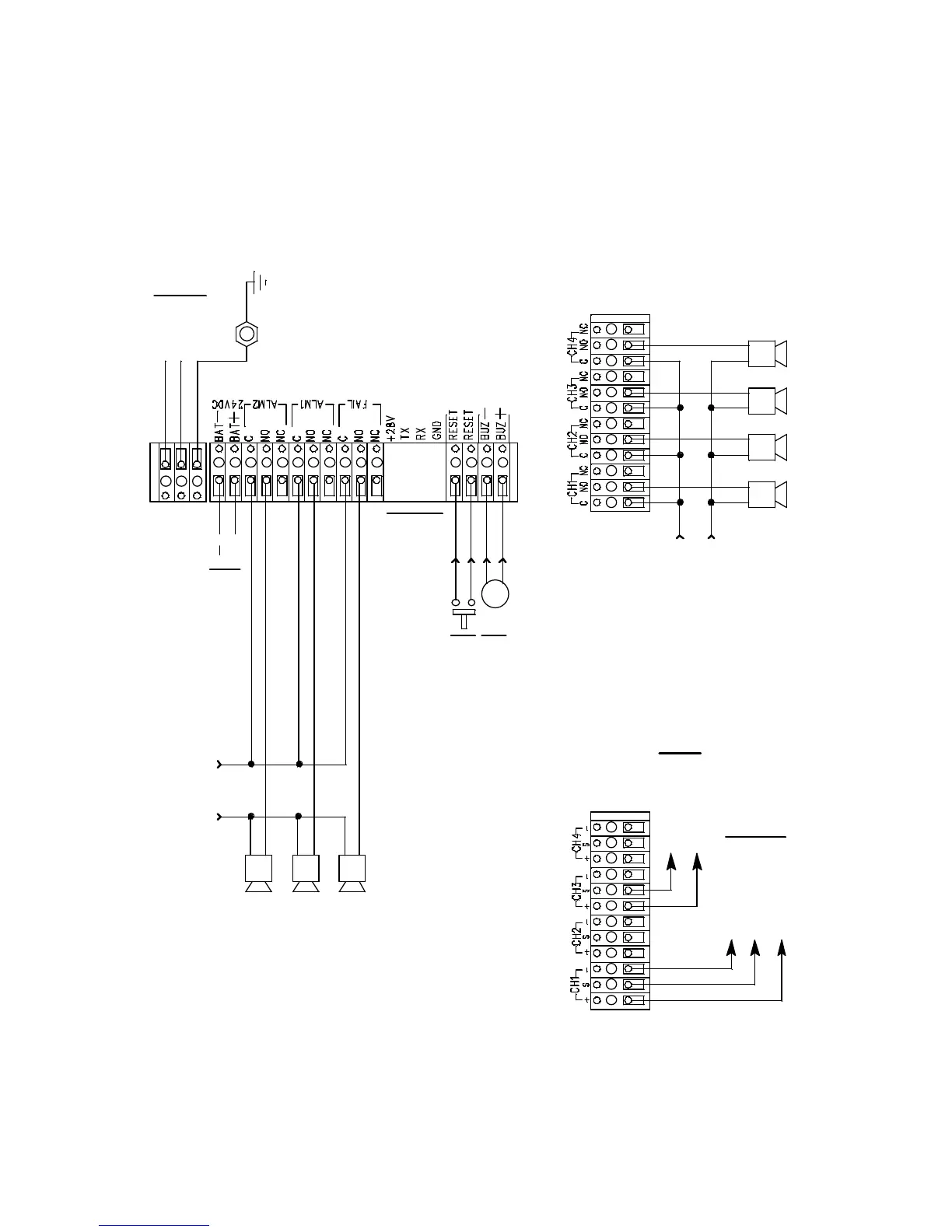
Do not connect AC
power if 24 VDC is the
primary power source.
(factory wired)
+
Alarm 1 Terminal Strip for
Channels 1 - 4 (typical wiring)
Not
Used
Alarm
Devices
2 wire 4 - 20 mA
Transmitter Terminals
(typical)
Buzzer
(factory wired)
FB (4 - 20 mA)
+ 24 VDC
-
(DC Ground)
Contact Rating of 10 Amps
Resistive at 250 VAC for Each
Set of Alarm Relay Contacts.
Alarm
Devices
Individual Alarm Relay Wiring
AC Power Wiring
Ground
Stud
Ground
Line (Hot)
Neutral
3 wire 4 - 20 mA
Transmiter Terminals
(typical)
FB (4 - 20 mA)
+ 24 VDC
Transmitter Wiring
Common Alarm Relay Wiring
(typical wiring)
Alarm Device
Power
Alarm
Device
Power
24 VDC
Battery
Reset Switch
(factory wired)